The Jim
Patchell Audio DIY
Webpage
First Posted
Updated
Audio DIY is something I have been doing since I was in high school. So, that makes it about 37 years now. Although, it has been a few years since I did a real serious project. Well, my stereo is getting old. So, it is time to start making some new components. But first, a little side project.
My brother in law gave me a KLH ASW80-80 sub woofer over the holidays. It is something he picked up at the TRW swap meet and he seemed to think there was something wrong with it. Well, in the end, it did check out OK, but, for what I wanted to use it for, it was kind of useless. I want to hook it up to my computer to use for the sound. But, I would need a separate power amplifier and crossover to use it. So, I decided to rip the guts out, build my own power amplifier module, include a good crossover, etc.
Well, I need to mill out some heat sinks and machine a panel. The panel is on the way. I have the blank heat sinks. I ordered a power transformer, a toroid. And I have started to lay out a PC board.
Schematic (pdf)(updated 2-06-2005)
Stay
posted, when there is more to show, I will put it up.
1-17-2005
Ok, now it is time to start blogging...I suppose. Today, I machined out the heat sink.
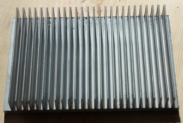
What I learned today while machining the heat sink
was that I need more tools for holding stuff down on my milling
machine. Oh, by the way, I did not machine out the fins.
This was a piece off of a large sheet of heat sink extrusion. It
was hard enough just squaring it up. That was another thing I
learned today. I could not figure out why I could not get things
to machine out square...turns out the combination square I have...is
not at all square. So, I need to get a new one of those, some 90
degree cast iron angles to hold stuff with while it is being machined,
some more clamps...
Oh yes, and I think I almost burnt out my Craftsman
Circular Saw. I use a cicular saw to saw pieces off of the big
sheet of extrusion. So far, this is the best way I have found to
do this. It is posible to purchase a hollow ground blade made
specifically for cutting aluminum...but it is still pretty rough on the
saw...
1-23-2005
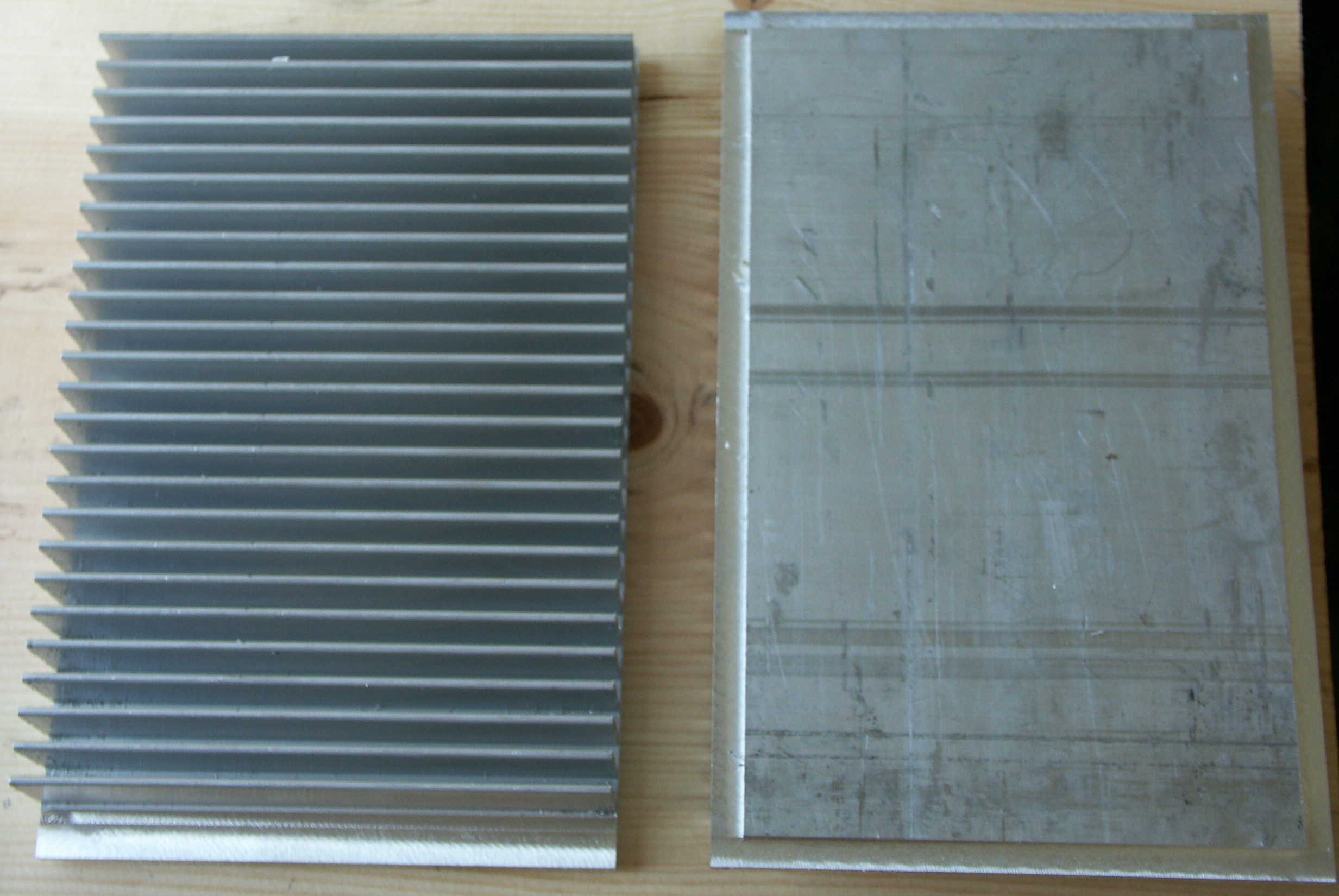
Looking at the part on the right, you will see where
I machined out a ridge. This will fit into a hole in the panel
that it will be mounted to.
Now this project was not exactly injury free.
If you combine one of these: 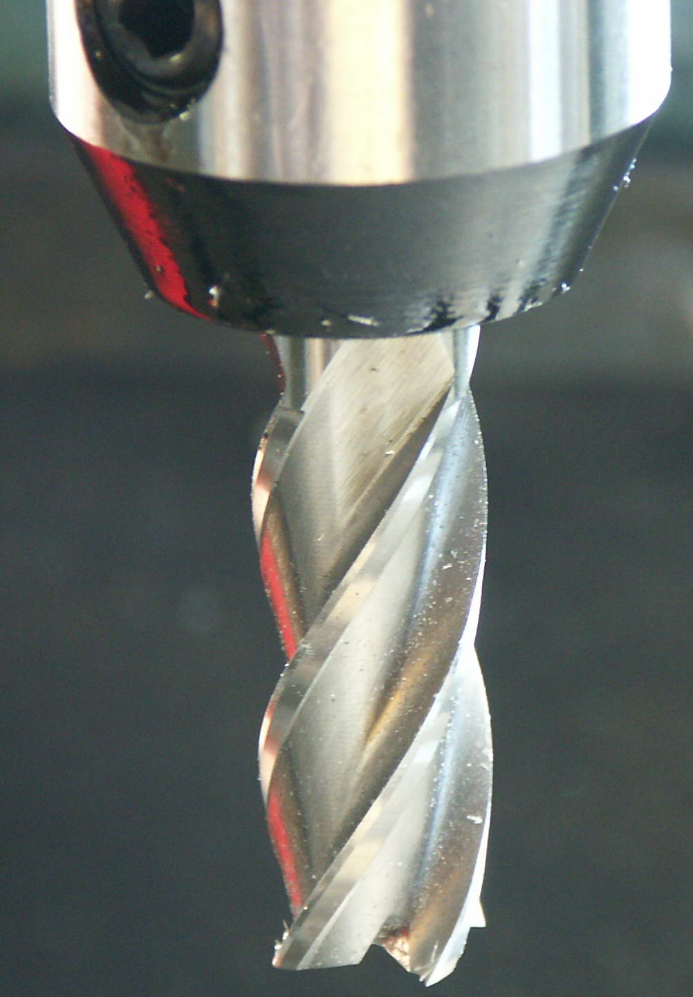 With
your hand, you get one of these:
With
your hand, you get one of these:  .
.
All I can say is OUCH! I was lucky in that the
end mill was not running. I got that cut from just a glancing
blow when I was doing the next setup for a cut. End mills may
look like a twist drill on steroids, but they are razor sharp.
Well, getting injured was more or less worth
it. I did complete, more or less, one panel/heatsink
assembly. There is still a little bit of machining left to do,
but all the hard stuff is done.
So, here is the panel all by itself: 
Here is the front of the panel with the heat sink
stuck into the hole: 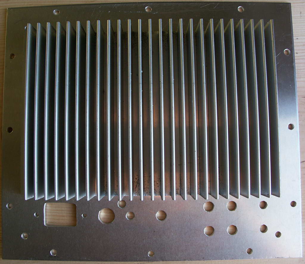
And here is a rear shot of the panel with the heat
sink stuck into the hole: 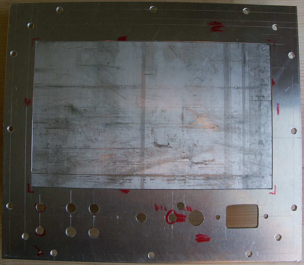
Well, that is probably it until next week.
1-29-2005
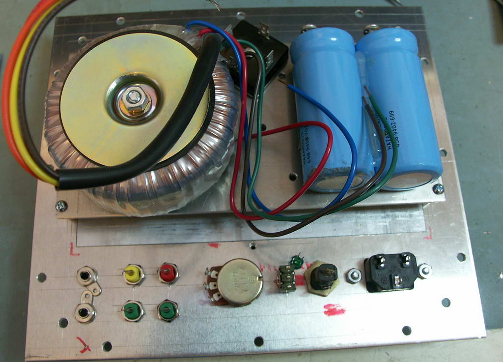
Well, today I have all of the
mechanical parts assembled together. My camera batteries died, so
one picutre I wanted to take I was not able to do. Still, here is
a rear shot of the panel with all of the parts on it. This
includes the power transformer, rectifier and filter capacitors.
They are mounted on a plate that will be above the printed circuit card
that will be fastened to the heat sink.

Ok, the batteries are charged now, so, here is what
the thing looks like with the panel inserted into the hole....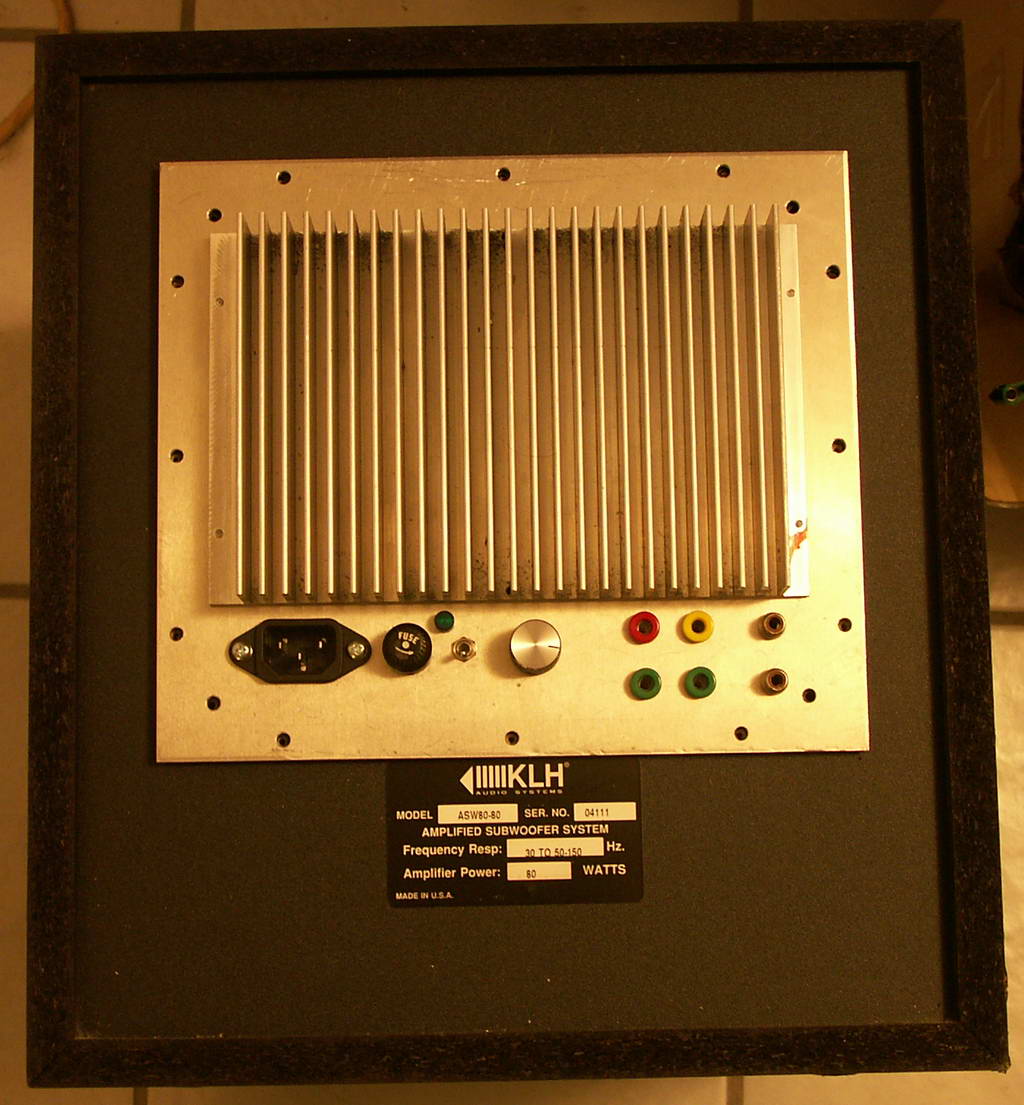
Well, I just finished the PC Board
layout. And here is its picture.
Now I just have to send it out.
2-06-2005
Well, just for the fun of it, here are
the CAM files for the audio amplifier. I generally don't post
these, for obvious reasons. I have no intention of selling this
board. So here they are.
Well, I got the PC boards back, and have almost completed two of them. I would have completed them except I forgot to order two parts. The 1K trimmer pot that adjusts the bias current, and the SilPads that will go under the power transistors. Bummer.

Mono Power Amplifier
This is my second power amplifier project. The basic circuit is similar to what is above, but there is only one amplifier per board, and no electronic cross over.
Schematic
Ancient Audio
DIY
Many years ago, in fact, starting in 1980, I was fascinated with doing a MOSFET power amplifier. Back in 1980 was about when complementary power Mosfets first started to appear on the scene. I tried many different topologies, but they all had problems. The biggest problem was thermal stability, a problem that I never solved to my satisfaction. Another problem was just the complexity of biasing the darn Mosfets. Well, here is the circuit that pretty much represents the best Mosfet amplifier I ever did. It put out a modest amount of power, somewhere around 20 to 25 watts as I recall. And it had a nice sound as well. Now, I would take everything you see in this circuit with a grain of salt. The diagram was drawn originally with the 16 bit version of the DOS based Orcad, version 4 I believe it was. So, that should clue you in how long ago this was, most likely sometime between 1992 and 1994. Also, you will notice there are no part values. Well, I can’t help that now. I gave this amplifier to a friend of mine, so I can’t even reverse engineer it. The two output devices were IRF9130’s and IRF120’s….I do remember that. Neither of these parts is available any longer. Still, somebody might get some ideas from the circuit, so here it is.
Old Mosfet Amplifier Schematic (pdf)