The
Jim Patchell Verilog and VHDL archive
Created
April 4, 2004
Updated September 27, 2013
Quadrature
Phase Detector
32 Bit -
Position Counter
Digital One Shot
6502 Core
Uart Core
Logic Analyzer Core
Delta Sigma
Converter
Vga Display
I2S Interface
Serial Multiplier
Adders Subtracters
Well, I
thought that these would be handy for other
people to use. And, if you are like I was when I first started to
post these, learning either VHDL or Verilog is not exactly the easiest
thing in the world to do. Most of these are going to be very
simple. And, perhaps, maybe not exactly the very best
implementation in the world. But, hopefully they should prove
both useful and educational. Now, you college students, don't let
me catch you cheating on your homework by using these ;^).
Probably, there will mostly be Verilog examples
here, since that is what I am actually attempting to learn. You
can also find VHDL examples elsewhere on this website.
Quadrature
Phase Detector
This module is used for looking at the outputs from
a quadrature encoder. This is intended for motion control, but,
of
course, could be used for other things as well. There are two
inputs, aquad and bquad, a clock input, and two outputs. The
count enable output will go true whenever an edge is detected on either
the aquad or bquad inputs, and the dir line will tell you which
direction you are going. These two outputs can be connected up to
an up/down counter to generate a position.
Verilog Code
This module is intended to be used with the above
Quadrature Phase Detector.
Verilog Code
This module is very simple. Although, I am
surprised by the number of people who never thought of doing it.
It has two inputs and one output. There is a trigger input
(called osin ), that will trigger the one shot on the rising edge of a
signal. The other input is a clock. The output will produce
a pulse that is one clock cycle long. I use this circuit for
synchronizing async signals up with synchronous circuits. Many
time
you only want the input to last only one clock cycle, depending on what
it is. I used to use this circuit a lot before there was
programmable logic, to any great degree.
Verilog Code
Example 4:
6502 CPU
Softcore
March 14, 2005
Ok, this is going to be a major project. What
I really want is a 68000 softcore, but that looks like too big of a
project to start out with. So, I will do a processor that is much
simpler first. I chose the 6502 because I used to use it a lot in
my projects, and am therefore fairly familiar with it, plus it is a
fairly simple processor. So far, I don't have a whole lot done on
it. I wrote the code for the 8 bit registers, and the code for
the address generator. I still need to do the ALU and the
Instruction sequencer. The Instruction sequencer is going to be
the most difficult task. One little mistake, and the whole thing
won't work...
Source Code for General Purpose 8
bit register
Source Code for Address Generator
Update:March
23,
2005
I have been working on the ALU off and on for a bit
now. Please keep in mind that I am using the Xilinx Spartan III
FPGA (an XC3S200 to be exact, on a Nu-Horizon Spartan III starter kit
board). For software, I am using the ISE Webpack, version 6.1
(yeah, a little dated, version 7.1 is coming out in a few days).
Now, the hardest part I am having to deal with is
the Adder/subtractor that is needed in the ALU. I have tried to
write Verilog code that infers an adder/subtractor, but only with very
limited success. And, when I look at the coding examples from
Xilinx, they seem to skirt around the very problems that I have
discovered that the synthesis engine doesn't seem capable of
doing. I have, in particular, not been able to generate a
subtractor with a borrow input and output.
This code is functionally correct:
always @(CI or AddSub or A or B)
begin
if(AddSub)
Y = A + B + CI;
else
Y = A - B +
!CI;
end
In that it does everything I want, but when you
compare the synthesized logic to what you get when you use the macro in
the library, it is a lot more logic.
So, to solve this, I wrote Verilog code to implement
the schematic symbol. For what ever reason, Xilinx has provided
no way to instantiate the adder subtractor in the library. So,
this seemed to be the best solution. I plan to make some mods to
the code to add additional functionality that I need.
Adder subtractor Verilog Code
Looking at the code in the above file is
instructive. I learned a lot about the structure on a Spartan 3
CLB when I did this.
Update:
April 10,
2005
Got some more work done of the ALU. I will
probably make changes to these files in the next iteration.
Also, as of right now, I have not actually tested this code.
Still, I am sure you will get the idea. A few of the comments in
the code may not exactly match what is actually being done...well, that
is just the way it is for now...once I decide what I am going to do,
that will change.
ALU Verilog Code
Status Register Verilog Code
The ALU also uses the above Adder/subtractor code.
Update:
April 11, 2005
I managed to do another module tonight...this one
connects the ALU up to all of the registers and a Data in bus and Data
out bus.
Registers and ALU interconect
First
Posted April 17, 2005
Well, I am finally making some progress on doing a
UART core...
Today, I finally got the transmit function to work,
which I need to do in order to get the recieve function working.
The transmitter is also the easiest part of the project. Even
when you are bit banging on a micro computer, the transmit is always
easier. Funny thing is, in verilog, you are bit banging.
There is not a whole lot to say about the
transmitter. It is not programmable. You are stuck with 8
bits, 1 stop bit, and no parity. You can easily change these by
chaning the code, but I was only interested in what you see.
Transmitter Verilog Code
Reciever Verilog Code
Update
April 17, 2005 at 6:31PM
I just got the reciever code done and you will find
a link to it right above. It was a good thing I did the reciever
code as it turns out there was a minor boo-boo in the transmit
code. I was shifting the MSB out first, instead of the LSB like I
was supposed to do. Anyway, it is all fixed now...(I
hope). There are still two things I need to do yet,
and that is to get the overrun and framing error bits
implemented. I may not ever do that...as I have never really used
these bits in any of my UART drivers anyway...
First
Posted April 17, 2005
Ok, now that I have a UART, it is time to start in
on a logic analyzer that I can build into the FPGA. Debugging
what goes on inside an FPGA is by far the most difficult thing to
accomplish. The solution is to use the internal memories that are
inside of the FPGA to record what the hardware is doing. This
data can then be read out of the FPGA and displayed on a PC.
Hopefully, very soon, I will have this code written...and hopefully, it
won't be too difficult to debug. It was bad enough trying to do
the UART blind, let alone something more complicated like a Logic
Analyzer.
I don't imagine that HP (Agilent) will be shaking in
their boots over this.
Update
April 23, 2005
Well, I have the first version of the Logic Analyzer
code written. There seems to be some problem synthesizing the
code as the buses going to the ram module do not show up in the RLT
schematic when I view it. This could just be a bug in the Xilinx
ISE software. I have seen similar things in the past and
everything still works fine...but I will find out as soon as I can try
this.
I still need to make an interface between the logic
analyzer and the RS232 port so I can download the data into my PC and
look at it.
Logic Analyzer Verilog Code
First
posted June 9, 2005
This is a Delta Sigma D-A conveter. It takes a
16 bit wide word stream and converts it to a single bit bit
stream. You can put an RC filter on the output pin and this will
reconstruct the signal into an analog signal. Now, until I saw
this work, I would not have believed it. I just constructed the
verilog code from a block diagram I found on the internet, and sure
enough, it does work. I do not know if this is the most efficient
way to do this, but what the heck. As of this first posting, I do
not know if this version of the source code actually works as
advertised. I originally did this at work, and retyped it in here
at home...so there may be a boo-boo in there. All I can say is
that it does synthesize with Version 6.1.3 of the Xilinx ISE
BaseX.
Delta Sigma Verilog Code
First Posted January 7, 2008
Updated April 17, 2008
This is a VGA display that will work on a Spartan 3
Starter Board from Digilent. This is a handy little proto board
with an XC3S200 on it that only costs (as of right now) $99. What
the code does that I have provided here is create a simple text based
display that will drive the VGA connector on the Spartan 3 board.
It is very simple. It will produce only 8 colors.
Each character uses 16 bits of data. 8 bits for the
character (1 of 256) plus an 8 bit attribute. The bits in the
attribute select foreground color, background color, invert and
character set (this allows up to 512 different characters). I was
going to have blink, but felt the extra characters were more
important...I may change my mind latter.
As of today, the first posting, I still have not finished the verilog
code, but it is real close. I am not sure when I will get around
to completing it. I am also providing a font editor that I wrote
using Visual C++ 6.0. This is a simple little windows app,
complete with source code.
This is all open source stuff...so have fun. And don't complain
to me about problems...(although, bug reports are always
welcome)....and no...I will not finish this if you have to turn in your
senior project by this Friday.... :-)
Font Editing Program
Xilinx ISE 9.1 Project for VGA Display
Update:
It should be noted that there is a problem
with the above project for Xilinx ISE. It seems that the file
that is loaded by the dpram2048x8 object (this is the character
generator rom), on my computer has the path e:\xproj\vga\chargen.coe.
Anyway...it would seem that this causes xilinx ISE to crash when
you try to compile. I will see if I can fix this sometime...but
it is posible, if you are clever enough, to fix it at your end (I
did...)....
More updates, I hope, soon....
January 24, 2008
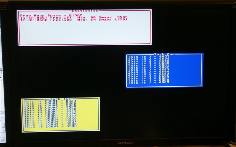
I have now got the VGA display actually displaying
text on an LCD monitor in 640x480 mode. I have even implemented a
hardware block move for making the characters scroll on the screen with
little overhead on the CPU chip. I hope I will be actually
posting the code real soon now.
April 17, 2008
Here is a photo of the video screen being driven by
the VGA display. I haven't posted this code, yet. But I
will post it soon.
I am running a version of curses on the AVR that first appeared in Dr Dobbs Journal around 1988 by Allen I Holub
(http://www.holub.com ). I had to modify it quite a bit. I
am going to have to wait for permision from Mr Holub before I can post
the curses library, but all the rest I will post. Maybe I will
just post a binary.
I2S Transmitter Interface
Posted September 21, 2008
Source code for I2S interface
This is verilog code for an I2S transmitter. This interface sends data to an I2S
reciever. The code takes a 16 bit word and sends it out.
There are dividers for setting up Mclk, Sclk, and LRclk outputs.
This of course means that what you connect up to is a slave.
All of these things can probably be changed easily...I would
hope. As of this posting, the code has been simulated, but not
actually tested.
16 by 16 Two's Complement Serial Multiplier
Posted October 15, 2008
Source code for Multiplier
This code is petty much a clone of the 74ALS384 serial mulitplier.
AMD called it the 25LS14...I believe. It is a very simple
multiplier. My implementation outputs only the upper 16 bits of
the product. This may seem odd, but that is what I needed.
It is easy enough to make it output all 32 bits. The source
code is in Verilog...
Adder Subtracter for Spartan 3/3E FPGA
Posted September 27, 2013
This is an adder subtracter using primitives so that I can get a very
small and fast little unit. This is sort of like programming in
assembly language. It is not portable to other devices than the
Spartan 3, but a lot smaller than I can get using pure verilog.
8 Bit Adder/Subrracter
16 Bit Adder/Subtracter
32 Bit Adder/Subtracter