Radio Projects
First Posted March 8, 2008
Last Modified March 13, 2014
I have been fascinated with building radios since I
was 13 (and that was in 1966) (See Below). One of the funnest projects I had
to do when I was a senior at UCSB was to build a super heterodyne radio.
Our goal then was to make the best radio we could. And mine
turned out very well. But I remember back to the days when I was
in Junior High and High school when I would build simple radios,
generally involving one or two transistors. And I also had fun
building AM transmitters. Several years ago I started getting the
bug again. My goal is to employ the experience I have had over
the last 30 years to help me build some fascinating radios with a
minimum of parts.
The projects I have in mind are a simple TRF
receiver using just two transistors, and also a simple superhet
receiver that will be pretty much completely scratch built. Right
down to the IF transformers. Although, that is not really so much
by choice. Getting IF transformers is not easy. And it
doesn't look all that hard to build my own. And that will enhance
the challenge of the project.
TRF Reflex Receiver
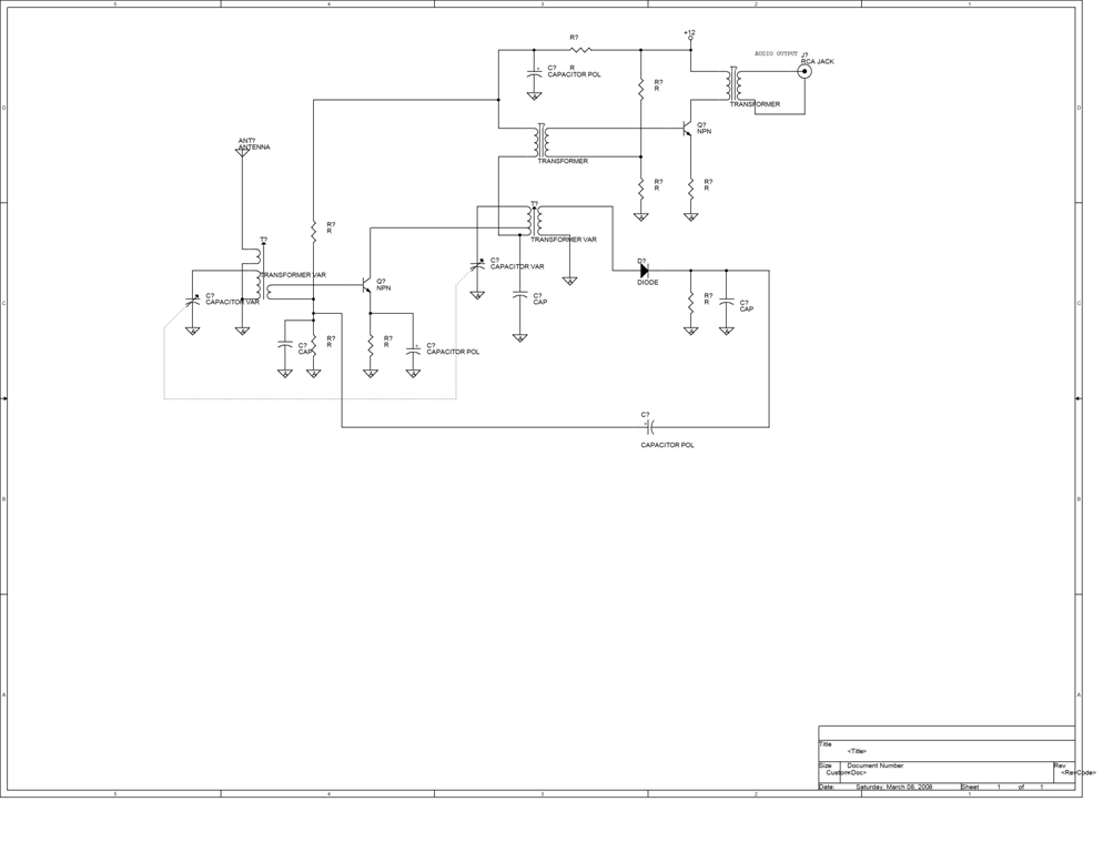
The above circuit...as of March 8, 2008, is very preliminary...and
untested to say the least. This is a double tuned circuit.
Both the input and output is tuned to increase selectivity,
although, this will make it more difficult to align. The two RF
transformers are going to be custom built. When the time comes, I
will provide details on how to do that. Of course...those who
think they can build it, I say, go ahead. There are a few things
I am sure that will have to be tweaked.
Simple Reflex SuperHeterodyne
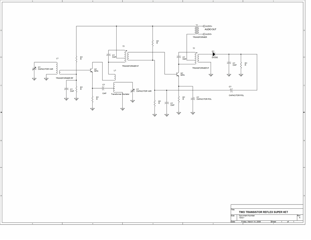
And this is a first cut at a two transistor superhet receiver.
This one is going to be interesting. First off, all of the
rf transformers are going to be built from scratch. The last time
I built a superhet receiver was when I was in college. That one
was a real doosie. Here I am going for minimalist.
Very Simple Broadcast Band Transmitter
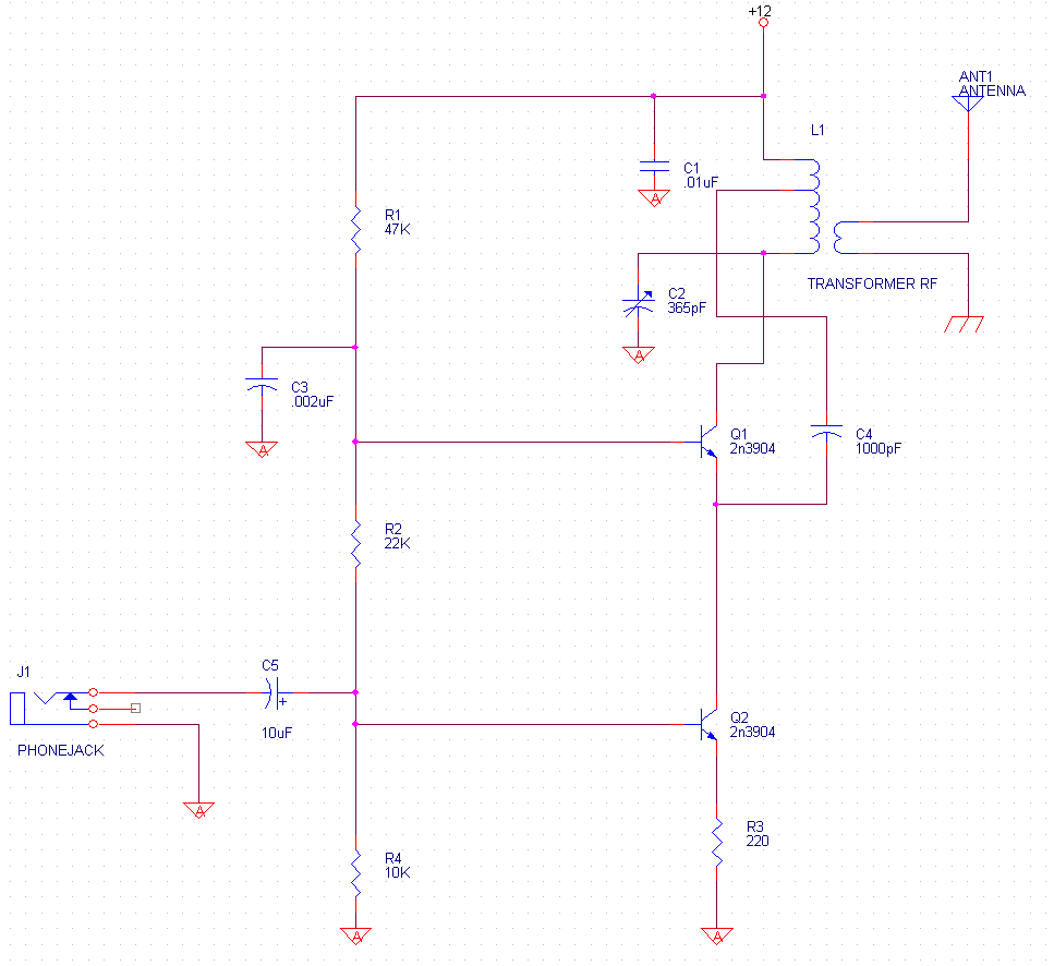 Common Base Oscillator with AM modulator
Now, how does this circuit work?
Starting with the oscillator, Q1 is the active device and is configured
as a common base amplifier. Components C1, C2 and L1 make up the
tank circuit that determines the oscillation frequency. This may
look a little different than what you normally see. C2 is a 365pF
tuning capacitor that is used to set the oscillation frequency.
It goes from the hot side of the coil (L1) to ground. C1 connects
from the cold side of the coil to ground. C1 is there really only
to insure that the cold side has a good path to ground at high
frequencies.
C4 provides positive feedback around Q1. It comes off a tap on
the tank coil so that the signal being fed back to the input has a nice
low impudence. It then feeds into the input of the amplifier,
which is the emitter of Q1.
Q2 serves two purposes. It provides the bias current for Q1, and
is also the amplitude modulator for the signal that Q1
generates. The AM modulation is achieved basically by having Q2
change the bias current depending on the input signal fed into Q2.
-----------------------------------------
Now, please be advised, I have not actually tested any of these circuits as of this time. I don't have time :-(.
One thing I have noted over the years of building radios is that they
oscillate. You can never get an oscillator to oscillate.
But it is no problems getting a receiver to do so. Radio
receivers must have a lot of gain in order to receive the weak signals
that are propagating through the ether. When you combine this
with all the coils and rf transformers, well, you have a recipe for
disaster. All I can say is good grounding techniques, careful
wiring, and shielding are your friends.
I hope to do so real soon. And I hope to have some real fun
projects that other may find amusing and educational. I have a
very soft spot in my heart for radio circuits, because this is where
the hobby started for me.
Here are some links for finding parts:
http://www.angelfire.com/electronic2/index1/index.html
August 23, 2011
Today, I finally ordered some chassis boxes and some
trimmer caps to start building and testing these projects. I plan
on building the super heterodyne receiver and the transmitter. I
still need to build another IF transformer yet, and get some more cans
for coil shields. But I am gradually gathering the materials that
I will need.
Winding Coils
First Posted March 15, 2008
Winding coils has never been one of my favorite things to do.
They almost always turn out looking very crude. But then I
remembered I have some pretty good tools. I used a piece of 2
inch PVC to make the coil form you see below. I cut off a piece
about 8 inches long so that I could chuck it in my lathe. #22
wire can be wrapped at about 33 turns per inch. The closest
thread I can cut with my lathe is 32 threads per inch, so that is what
I set it to. I made two passes so that I could make fairly light
cuts to keep the plastic from melting. Then using a cut off tool,
I trimmed off what I needed.
I then used a #60 drill to make the holes that the wires go through.
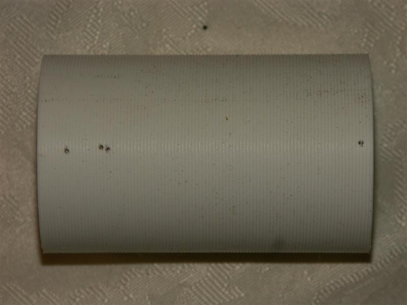
Then I got out my spool of wire and began winding the coil. With
the thread pattern cut in the form, winding was a lot easier. It
wasn't too much problem keeping it looking fairly neat. Although,
it was the little tickler coil that was the hardest to wind, for some
reason. I wasn't able to keep a hold of the wire and had to start
over twice. The big coil I got the very first try.
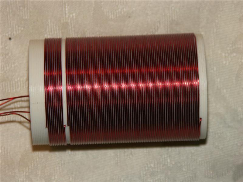
I intend on using this coil in an RF generator.
August 19, 2011
Well, you know, to use radio coils in anything that has some gain, the
coils will need to be shielded. But, how can this be done easily.
Got the answer at the local Michaels Craft Store. They sell these
cans for putting homemade Christmas goodies into. What I saw was
the perfect thing to put an RF coil into.
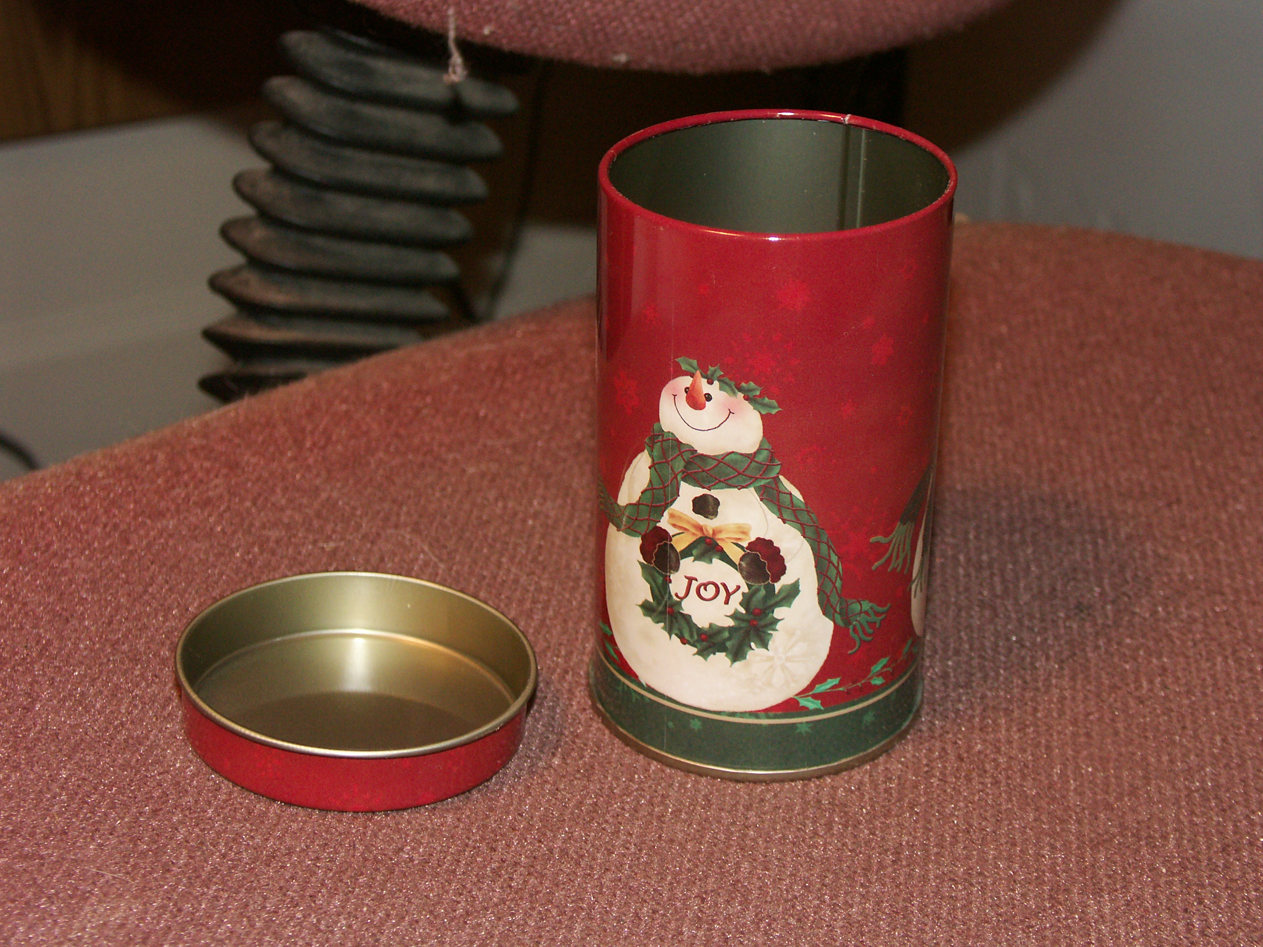
I will probably have to sand the paint off where the cans join for good
electrical conductivity. What I plan on doing is bolting the lid
down to the chassis. Then I will mount the coil on top of
that. Then, just press the can over the lid. Yeah, I know
it may look just a little too cute...sure beats having to fabricate
something like this.
Building IF Transformers
First Posted July 7, 2011
Hey, it is been a while since I have updated this
page. Well, last time I posted, I could still see. Things
are a lot more tricky for me now.
But, I am trying to forge ahead with my radio projects. And I
need IF transformers. There are several ways to skin this cat.
http://www.angelfire.com/electronic/funwithtubes/IF_Can-1.html
http://www.lulu.com/items/volume_65/7219000/7219361/1/print/7219361.pdf
http://m0xpd.blogspot.com/2009/12/if-transformers.html
The above are two other links I have located on building IF
transformers. Either of these methods will work. I am going
to outline another way to accomplish the same thing. I cannot say
my way is any better or not, but what the heck.
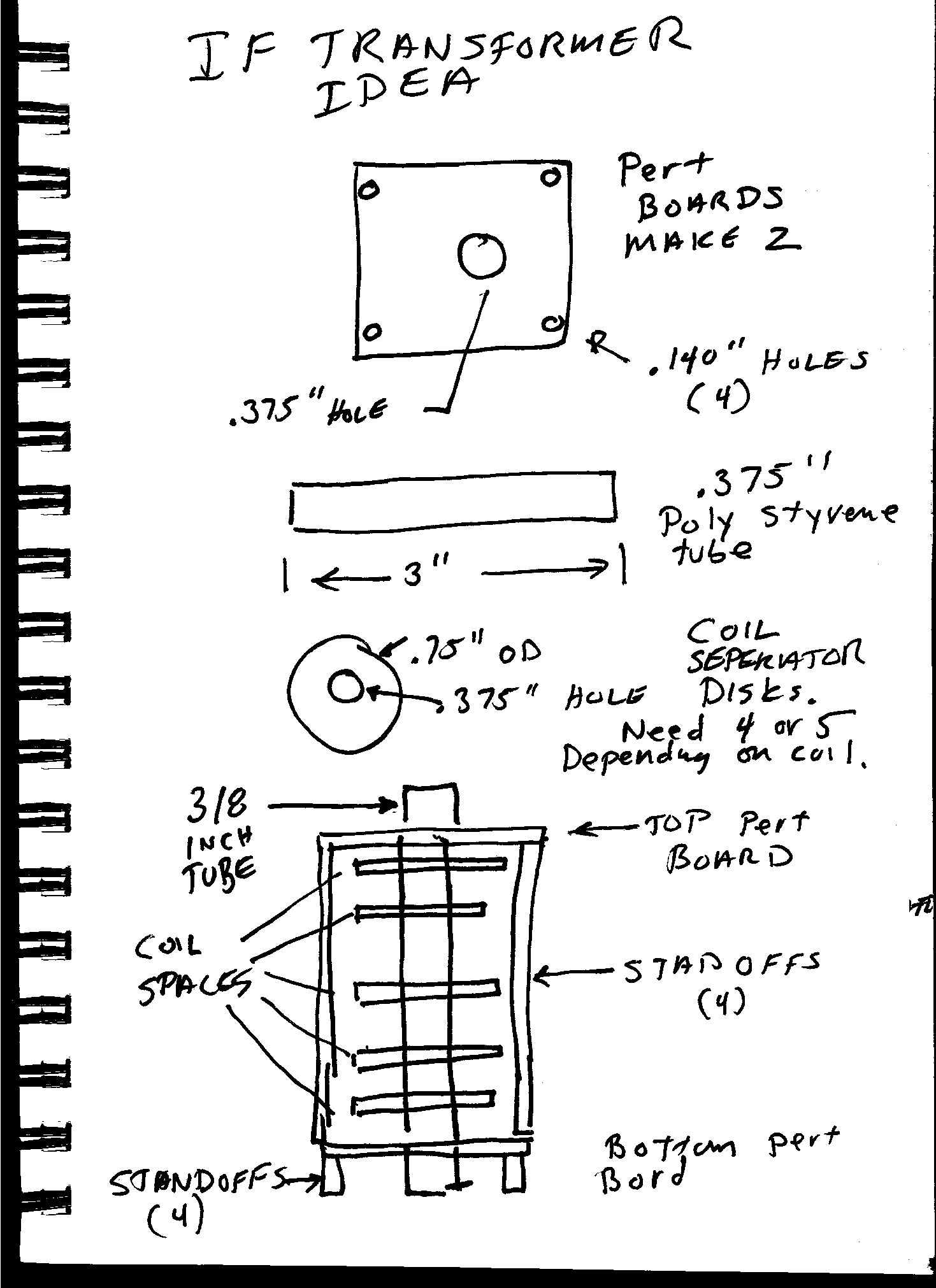
The IF can is going to be made of a 3 inch long piece of 1.75" square
aluminum extrusion. The stuff I purchased has .125 inch thick
walls, so the inside is 1.50" square. The coil for is going to be
made from 3/8" evergreen polystyrene with3/4" by .060" thick disks to
keep the coils in place. The top of the can will be a 1.75"
square of .125" aluminum.
This is going to be kept together by using threaded spaces. The
spacers will hold two .062 fiberglass perf board apart. The perf
board will have a 3/8" hold in the center. The coil form will
pass through these two holds. On the top perf board I will mount
one or two trimmer caps, depending on the type of transformer, to tune
it. The whole mess will be screwed together hand hopefully look
pretty clean. I have ordered the materials for this, so I am
hoping I may actually get a chance to build a few samples soon.
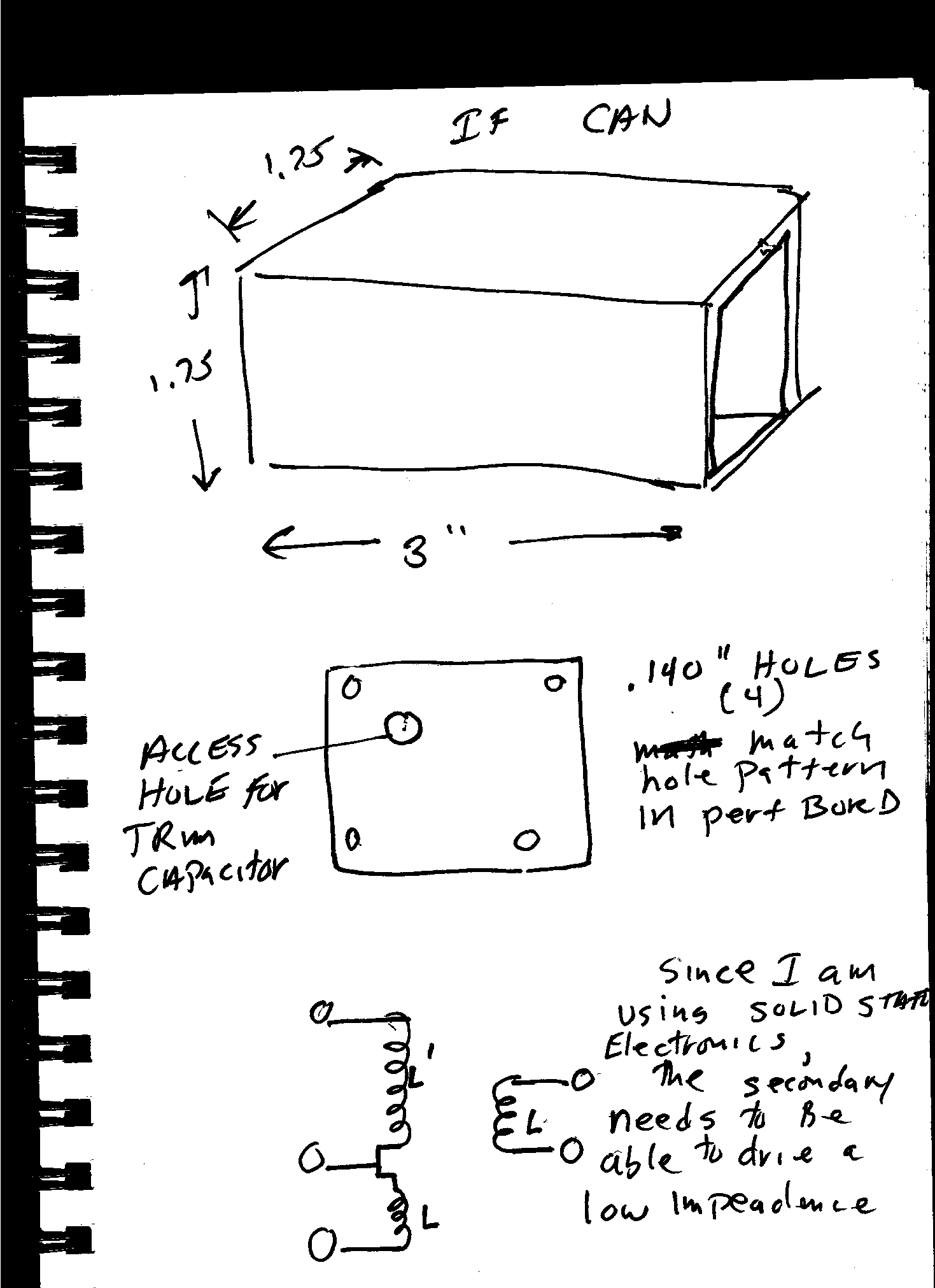
Hey, these drawings don't look too bad. On
screen, I can magnify them. But, I see at least one
omission. There should be a capacitor across the primary winding
(the one with the tap). I was planing on using a fixed cap in
parallel with an adjustable trimmer. The cap will go across the
the entire winding...i.e. will not be connected to the tap. My
intention is to mount the "interior part of the transformer down to the
chassis. The 1.75" sq extrusion will slip over this, and then the
lid will be screwed on top, into the top of the interior part of the
transformer, and this will hold the whole thing together, I hope.
August 12, 2011
Ok, today, I actually started building the IF
transformers. Today, I made the IF Can sides. It is just an
aluminum extrusion cut to size.
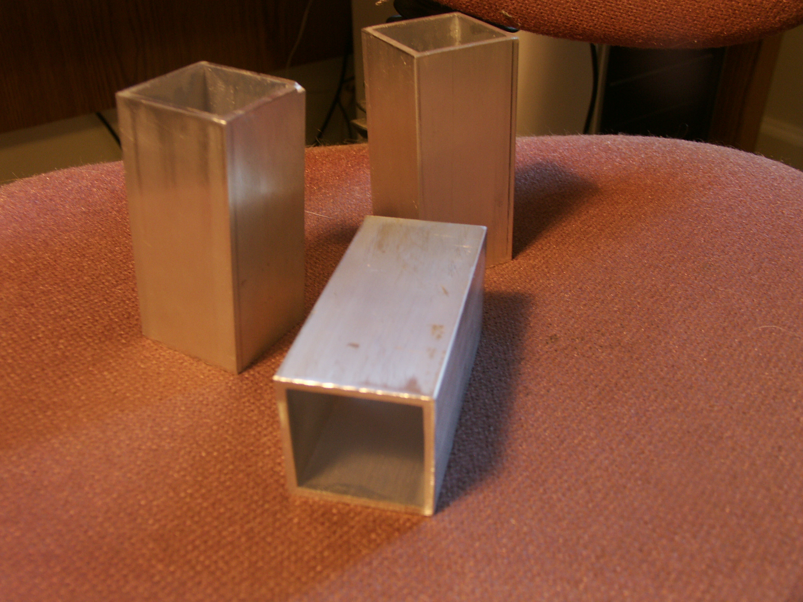
These are the first three I cut out. I just
cut them with a hacksaw, and then cleaned them up with a milling
machine. And then a little filing with a single cut file to make
things smooth. This was, I think, the HARD paart.
August 13, 2011
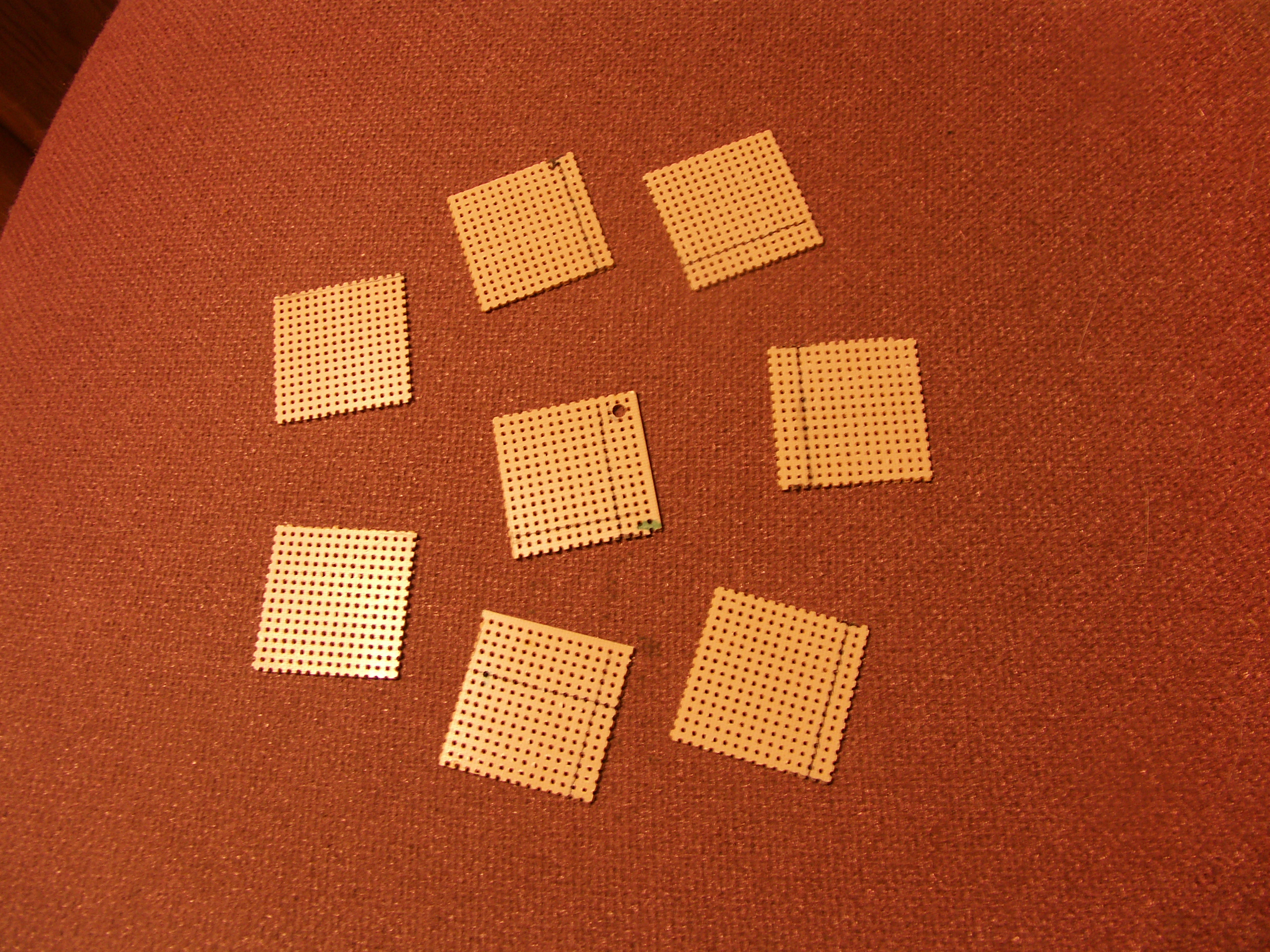
Here are the perfboards, before they are drilled.This was a real quicky
tonight. The boards are 1.5 inches (about) square. I will
clean them up with a file later to get them more exactly to the correct
size.
August 16, 2011

Above, you can see the perf boards after they have
been drilled. Most people out there probably could have drilled
them quite easily. Not me. Because of my very low vision
(20-200 uncorrectable), I had a very hard time drilling the holes in
the correct place. I solved this by drilling a pilot hole that
was about .08 inches. I could see this much better. But I
also had to use a brad tip drill that was 0.140 inches in the drill
press. I would use the brad to locate the pilot hole, then I
would turn on the motor in the drill press. I took me about 3
hours to make to two little boards. The tube was easy. I
just cut the 3/8 inch dia tubing in my miter saw.
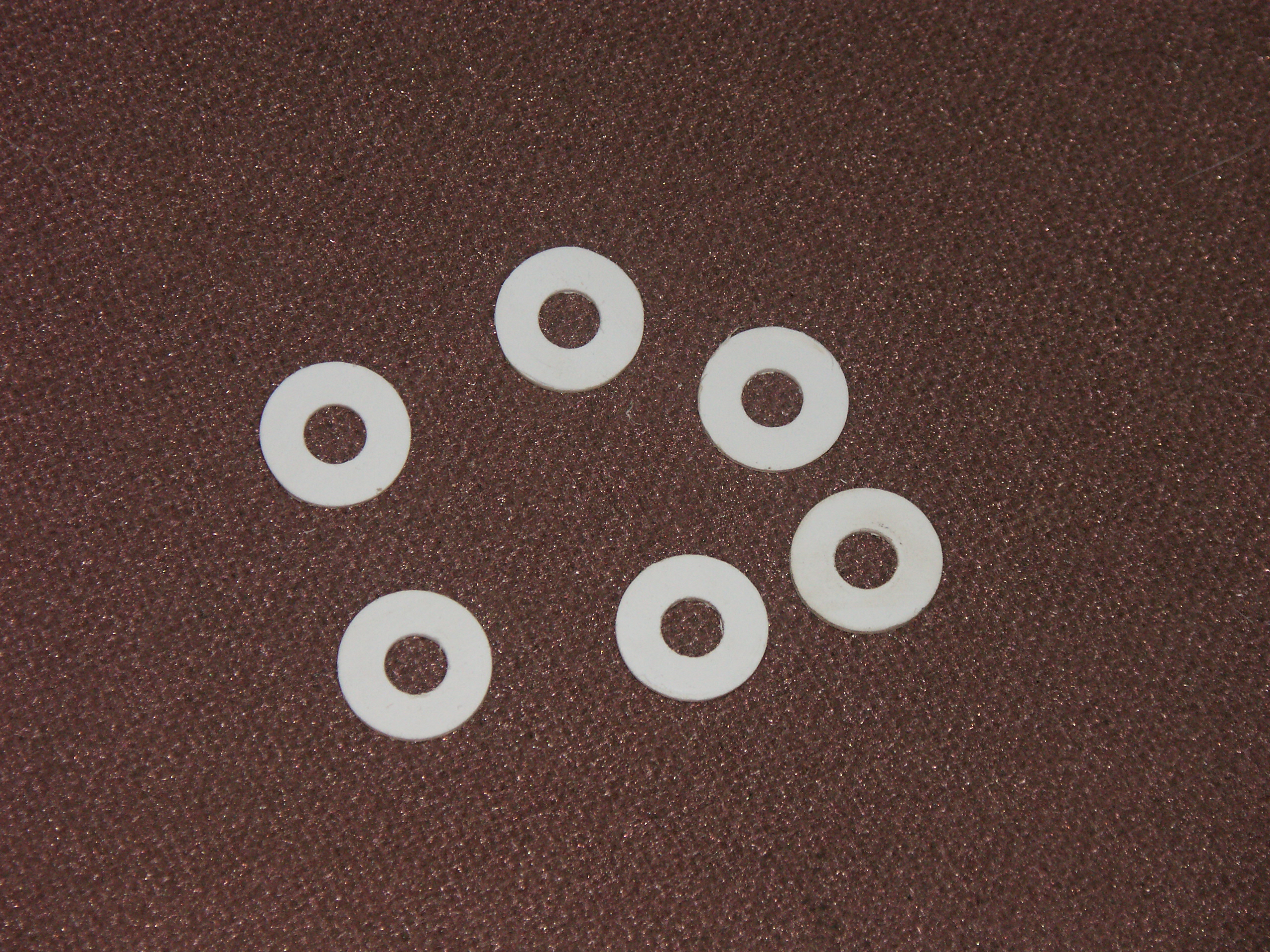
The washers were easy to make. I clamped a
sheet of 0.060 inch thinck styrene on the X-Y table of my milling
machine. I put a drill chuck in the quill and started with a 3/8
inch brad tip drill. I drilled a hole every 1.500 inches. I
thin put a hole saw in the chuck and went over the same places
again. The guide drill in the hole saw is smaller than 3/8 inches
so really, I was only using the saw part. I drilled slowly,
trying to keep the styrene from melting. This was pretty tough to
do with the hole saw. So, after I got the rough cut washers, I
put them all on a 3/8 inch bolt, and held them together with a
nut. I then chucked them back up and used 100 grit sand paper to
smooth them down. Use a very light touch. Things can get
hot very fast.
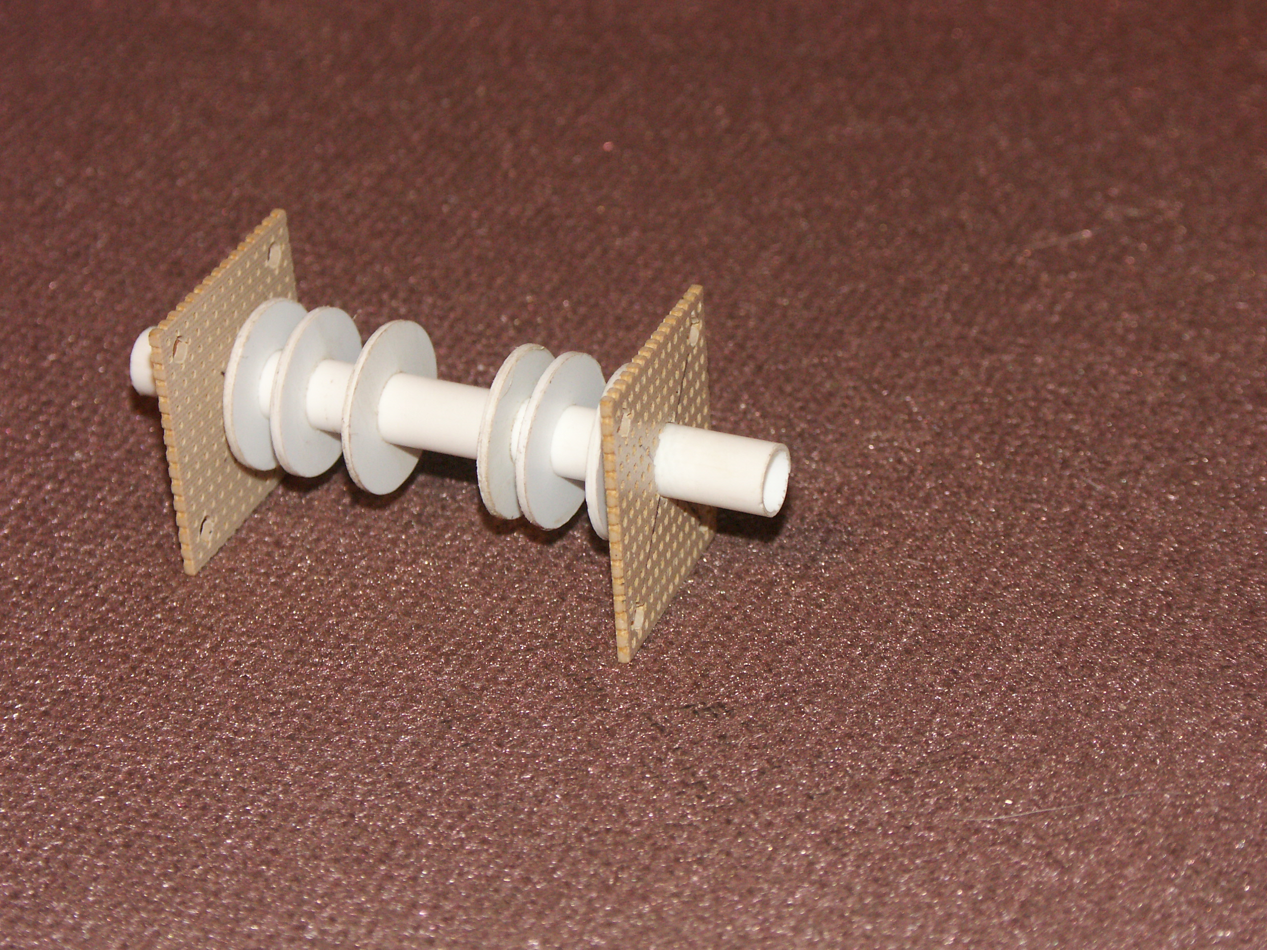
Here is the perf board and coil form all put
together. I still need to get some spacers to hold the whole
thing together. As of tonight, the only real peice I need to
fabricate is the lid that goes on top of the can. This is another
job that is NOT going to be easy for me.
August 17, 2011
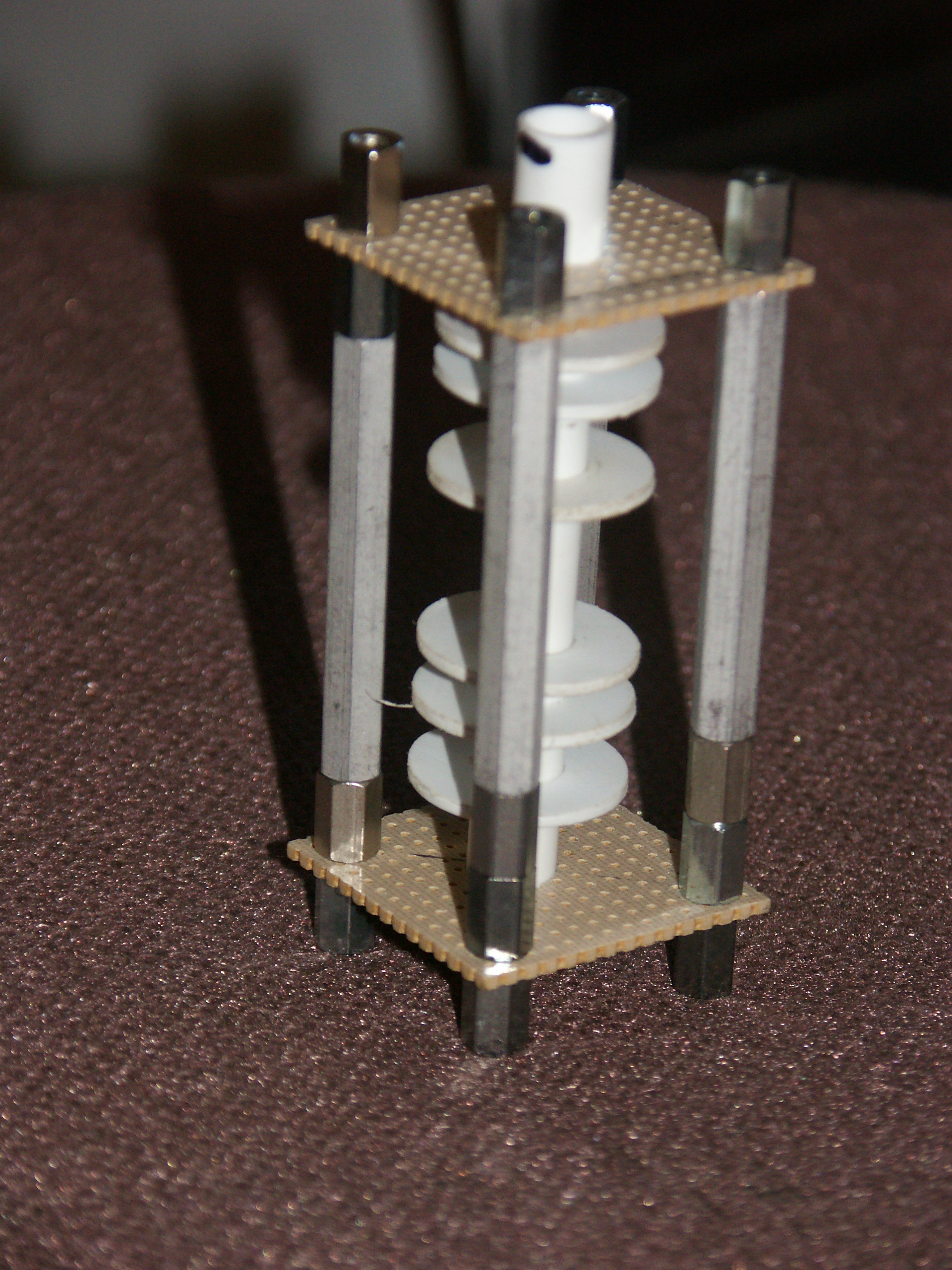
So, close, I can taste it. These are the main
mechanical components for the inside of the IF transformer all put
together and ready to put inside of the can. The standoffs on the
bottom will be bolted to the chassis, and the standoffs on the top will
hold down the lid. Now, I just need to finish the lid. I am
not looking forward to that task. It is going to be a very tough
thing for me to make.\
Morris Coilmaster
July 9, 2011
Did a lot of research today for a book on building
radios. I was looking into coil winders. It turns out, that
somewhere in my collection of stuff I do have a Morris Coilmaster
universal coil winder. Didn't even really know what it was.
No, I need to find it. I sure hope it is not lost. I
ordered a booklet from Lindsay Publication on building a clone of this
device. I am interested in that partly because I need to make
sure that this is something that everybody would have access to one way
or the other. It seems pretty evident that nothing like this is
made today. It also has gotten me thinking that an NC version
could be built with a couple of stepper motors. With stepper
motors, one would not have to mess around with gears and cams. I
am pretty sure that some sort of coil winder would sure make my IF
transformers a lot more cool. And a universal coil winder will
help to make the Q of the coils that much better.
July 10, 2011
Hey. I found my Morris Universal Coil Winder.
It is missing at least one spring. Hopefully I can replace that.
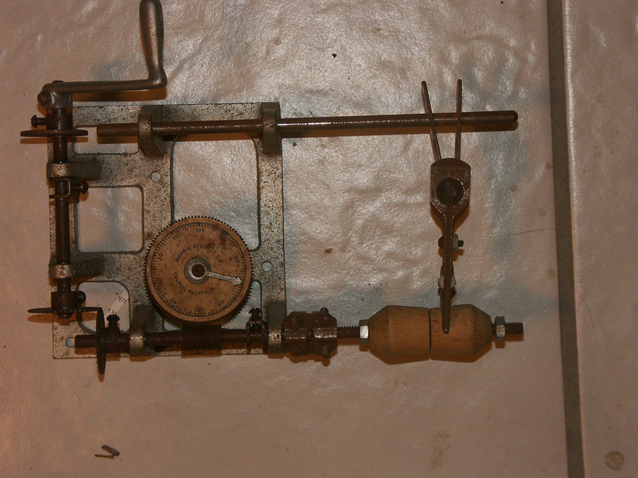
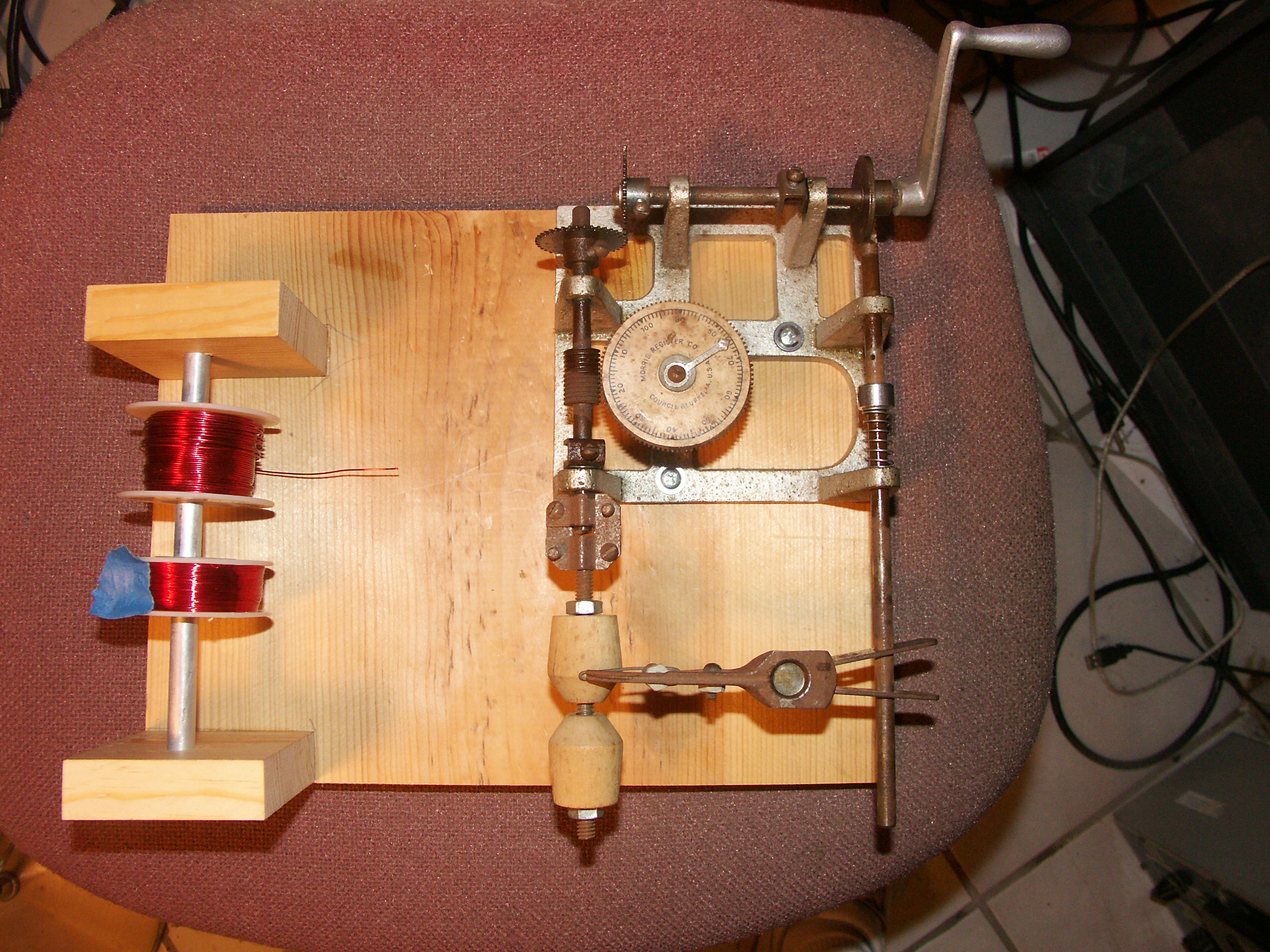
August 7, 2011
Well, today, I managed to whip the Coilmaster back
into shape, more or less. It is going to take a bit more
work. I replaced the missing spring and very lightly lubed the
bearing points. I also mounted it on a wood base, and added a bar
to put the wire spools on. The big problem is the shaft coupler
for the screw that holds the coil form. I can't seem to get
it to hold the scdrew on in any way shape or form that is
straight. I also did not have anything to put on the wire to make
it "sticky". Hopefully, I can pick up some bee's wax. The
coils I managed to wind today were, well, not impressive. My
reaserch has suggested that getting good coils will take a bit of
practice. Anyway, here is a picture of what it looks like:
I am still doing research into building a NC coil winder, but it is
rather obvious that I need to learn my chops on this hand powered unit
so that I can know the best ways that coils can be constructed. I
have to say that the video I saw on You tube using a similar machine to
the coilmaster to wind a coil was quite impressive. And there is
obviously something I am missing here.
Building Your Own Variable Capacitors
First Posted July 18, 2011
Now, here is a very high goal to achieve. I
have been doing a lot of research on this subject and have found quite
a number of poeple that are already doing this. Some of the
results are quite spectacular. Some of the results are more
crude. However, all pretty much seem to be functional. I am
trying to come up with a way to make an effective variable capacitor
that does not require fancy tools. I don't know if this is
possible.I would rather not make the plates out of soft aluminum.
But, working with harder alloys is a lot more difficult. Plus, I
have very limited vision, so what ever I do must be something that can
be done blind folded. If I can solve this problem, then just
about all of the major components in the radio can be scratch
built. A very exciting thing for me at least.
July 28, 2011
I have been doing some more thinking on this problem. I am going
to try and come up with some sort of a jig that will make cutting out
capacitor plates "easy". I still have no idea how I am going to
do this. By far, the best way is to build or gert an NC mill, but
this is not very simple or inexpensive. I will keep working on
this problem. There has to be some solution..
One Transistor Super Het Receiver
First Posted July 18, 2011
A one transistor Super Het? Ha! Not
Possible. Or, at least that is what I would have said up until a
few days ago. In doing my research, I ran across a circuit for
just that. It consisted of an Antenna Coil that feeds into a
transistor that is also connected to an oscillator coil.
Pretty much like the normal converter stage used in a typical
transistor radio. But, this is where it ends. The converter
stage outputs intio an IF transformer. There is no IF amplifier,
however. The transformer goes directly into a detector. The
output of the detector then goes back into the converter
transistor. So it is a reflex receiver, but I have to say, it is
a bit strange.
So, now I see the challenge. I am now going to
have to see if I can come up with something similar. I thought I
was veing very clever by doing a two transistor reflex superhet (see
above).
Radio Projects from my Past
First Posted August 23, 2011
I did not think that anything from my electronics
past existed any more, but I was wrong. My older sister arrived
yesterday from Seattle with a box of stuff that my mother kept from
when I went to school. In that stuff was the Journal we were
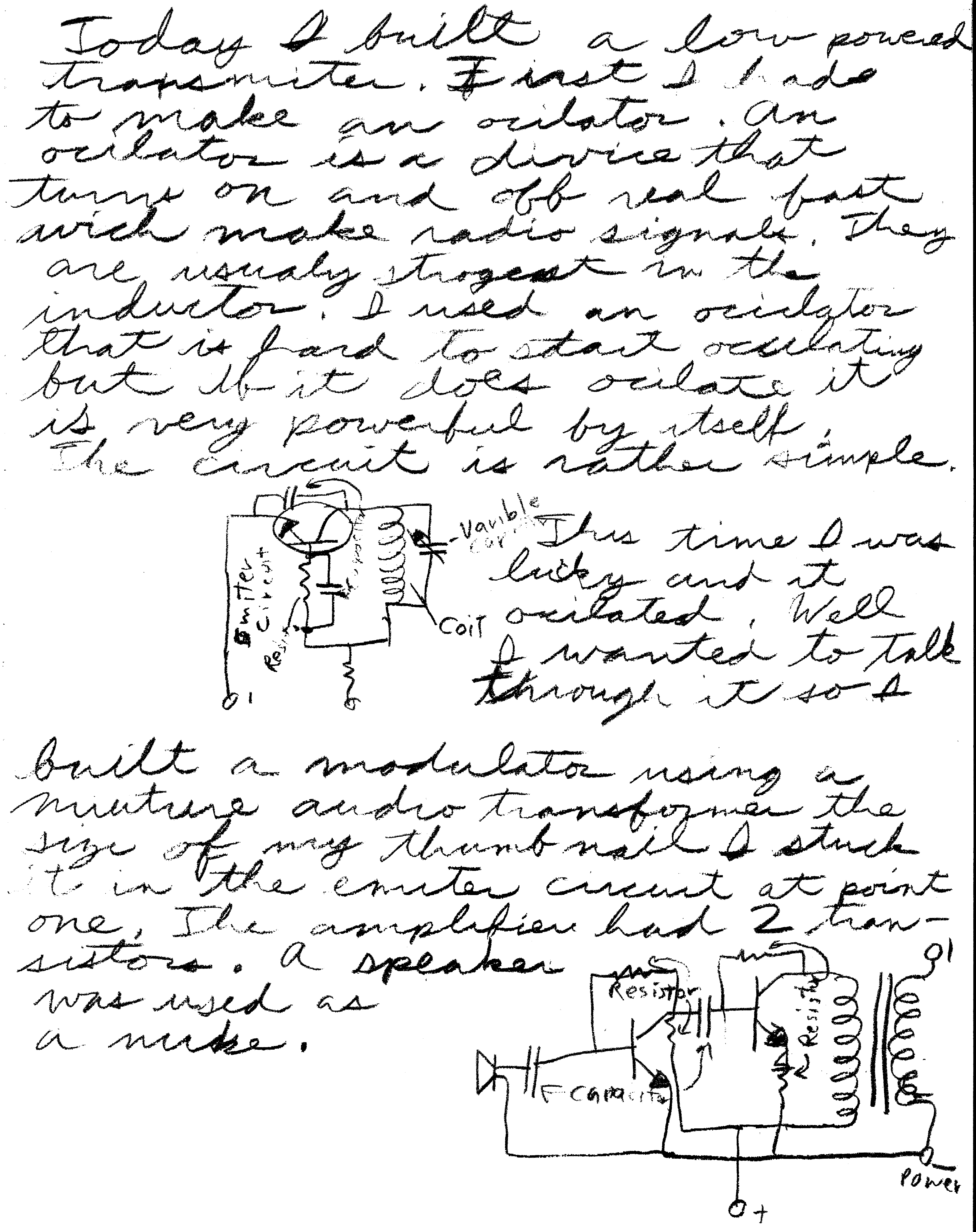
supposed to keep in my English class. So, I wrote about things I
enjoyed. The first thing was about the transmitter I was working
on at the time. For a time frame, this is when I was in the tenth
grade. Most likely, this was the spring of 1969. I am
pretty sure that the journal was one of the last things we did in that
class. Anyway, here are those pages for your amusement.
This project was partially built in the electronics class I was taking at Dos Pueblos at the time....
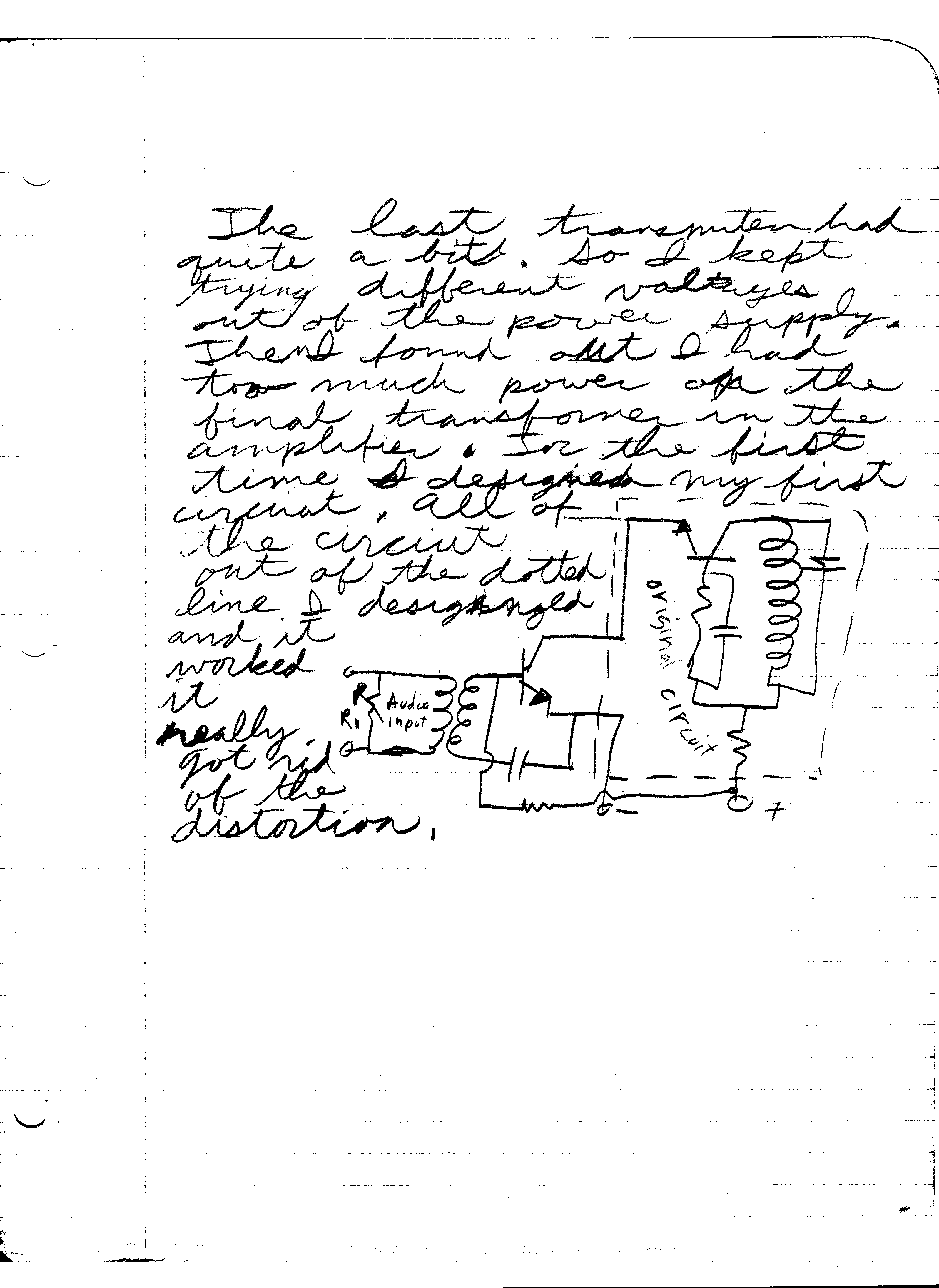
Commentary.
After reading the text, I have to say I am not
really too sure exactly what I was trying to say. The circuits,
however, are fairly plain. I can sort of see why I would have a
hard time getting this thing to work at times. The transistor
biasing is, well, just not very good. The bias current would
depend very much on the characteristics of the part used. Still,
you can see the basic circuit. It is very similar to the one I
show above.
LC Circuit Calculator
First Posted September 11, 2011
Updated March 13, 2014
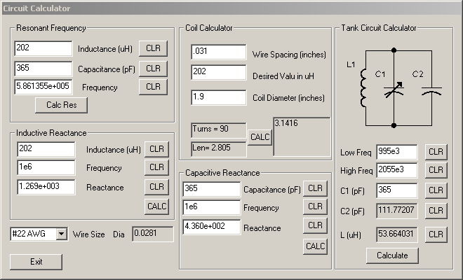
This is a handy dandy program I created to make it easier for me to do
the mundane calculations for the radio projects I am doing. There
are four calulators in the program. There is resonant frequency,
capacitive reactance, inductive reactance, and a coil
calculator. The coil calculator figures out the length, number of
turns for a given coil value. These are single layer solenoids
only. And even then, this is only an approximation. Source
code is included. This program was compiled with Microsoft Visual
C++ 6.0.
March 13, 2014
I added some calculations for determining the
inductor size and the pad capacitor size when given a tuning range and
a maximum value for the tuning capacitor.
Circuit Calculator
This program is in the public domain and is open source.
Electronics Books that I enjoyed and Influenced me, and some contemporary Books
First Posted October 2, 2011
When I was younger, there were a lot of books I
enjoyed. Most of them, however, I don't remember the names
of. A few I have been able to locate. Some, I am sure, I
will never locate. Anyway, here is my list.
Using Electronics by Harry Zarchy
This book is one of the ones that I considered the
most fun. It mostly deals with radio receiver circuits. All
of the circuits are pretty basic. It should be noted that several
of the circuits probably will not work with modern transistors and will
require modification. Many of the circuits have no bias for the
base of the transistors. Back in the 50's, you could get away
with that because the transistor junctions leaked so bad the base would
bias itself. And in some cases, in order to work, some of the
circuits require a germanium transistor.
Now, it just so happens that the only copy I have is electronic. So here it is (see above).
A Boys First Book of Radio Electronics by Alfred Morgan.
I am still trying to get a copy of this as well as the three books that followed it.
Contact Information: patchell AT cox DOT net