The Digital Synthesizer Module Number
One
DSM1
First
Posted July 16, 2005
Updated February 7, 2009
I am not sure exactly what form this project is
going to take yet. My original concept was to make an addon board
for the Xilinx
Spartan 3 Starter Kit. The Starter Kit board has an XC3S200
part on it. It appears that maybe this board is just a little bit
too small. The 200K gate part is just not going to be able to do
all I want it to do. It would seem that I will need to use at the
very least the XC3S400 part. But I am not giving up yet.
You may ask why I am using Xilinx. Well, the biggest reason is
that Xilinx seems to be just a little less expensive to play
with. I have nothing against the Altera parts. And you can
probably apply what I hope will soon be posted here to those
parts. As soon as I can locate a Cyclone II eval board that I
like, I will probably dive into that part as well.
You may also ask why an FPGA? Why don't you use a DSP like Clavia
does for the Nord
Modular? The answer to that is I think the FPGA will be more
fun. Also, the FPGA has a lot of raw horse power that is going to
be difficult to achive even with the fastest DSPs.
What are my goals?
Right now it is to create a set of hardware that I
can easily experiment with producing digitaly created sounds.
Some of the basic functions that will need to be created will be
Oscilator banks, Filter banks and envelope generator banks. These
are probably the most difficult functions to do. One thing I
don't know how to do at the moment is to create a way that modules can
easily be interconnected. However, creating large quantities of
the above elements is going to be relatively easy. Creating 512
32bit oscillators should be a piece of cake. Doing on the order
of 128 filters should also be fairly easy.
June 22, 2008
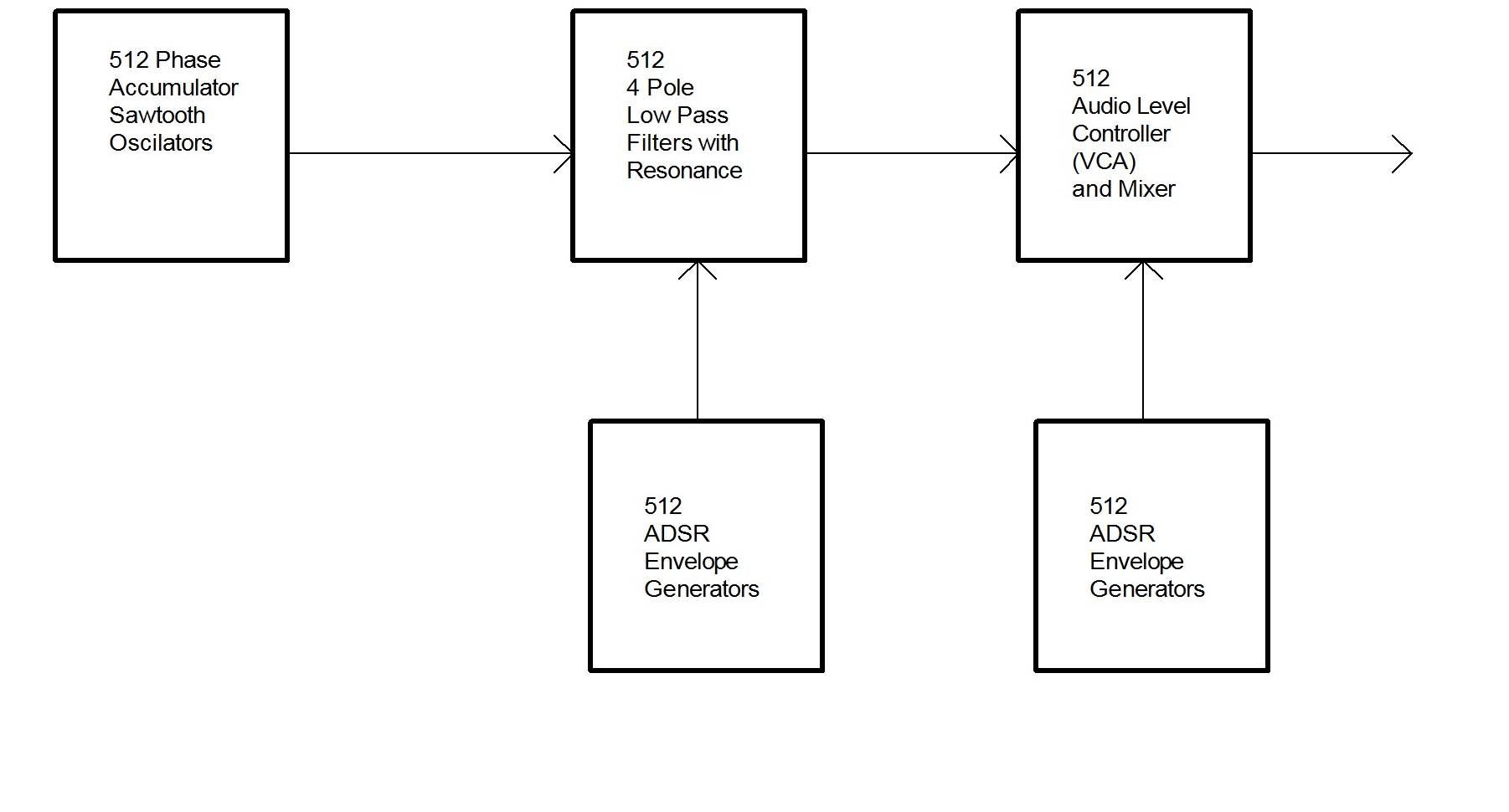
Here is what I have in mind for the moment. This, I propose, to
implement in a Xilinx XC3S1000 fpga. I am going to use a Diglent
Spartan 3 Starter board with that part mounted on it. This should
be able to cover all that is proposed. I will be controlling it
with an Atmel ATmeaga2561 microcontroller.
I should be able to run this at 96KHz sample rate, my goal is, however,
to run at 192KHz sample rate. The tough one is going to be the
filter. I am currently writing the code of the low pass filter.
I know that 512 of anything seems like a lot, but, that is just
sort of how things break down in the Spartan 3. If it works...I
don't think I will need to worry about running out of oscilators.
I still need to figure out some way to get modulation into the
picture, but, that I am sure will come later. I want to get the
basic system down first. It would be kind of keen to be able to
do FM modulation from channel to channel...
September 18, 2008
Well, I am making progress...although, you would
hardly know it. I ordered some delta sigma converters yesterday.
These are very small and simple converters, but they should get
the job done quickly. I also ordered some SOIC-8 breakout boards
from Spark Fun to mount them on. Spark Fun is a really great
place. Where do I stand? Well, as of right now, I have got
nearly all of the windows program done that I am going to use to test
the hardware. The firmware also is nearly complete for testing
the hardware. So far on the hardware, I have got the oscilator
section done, and am now starting on the ADSR generators. I also
have a very simple logic analyzer function running that is going to aid
in debugging the various pieces of hardware. Once I get the
Envelope generators running, the job is about 1/2 done. I have
high hopes for this project...I am sure there are going to be a few
disapointments...but I am optimistic.
October 2, 2008
Still making progress. Today, I got the
envelope generators working. So, in the above block diagram, I
have two of the five blocks working.
Here is a phote of the set up I am using to develope the code on:
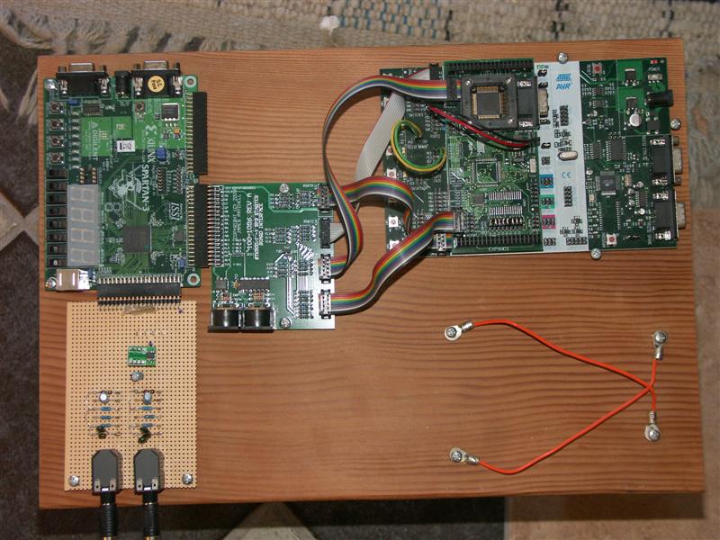
What you see is an Atmel STK500/501, an Atmel JTAGICE MkII, a
custom interface board, a Xilinx JTAG probe, and a Spartan3 Starter kit
with an XC3S1000 on it.
I have also been writing a windows program for debugging the hardware....here are a few screen shots...
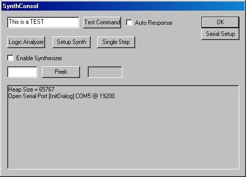
This is the main dialog.
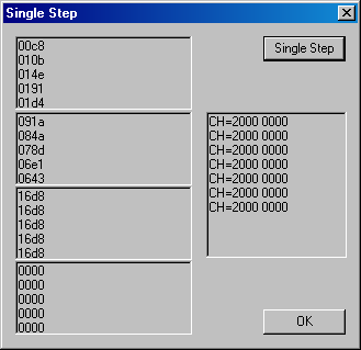
There have all been a great aid in getting the verilog code debugged.
Again...as soon as I get it more or less done...all of the source code for this projects will be posted.
October 8, 2008
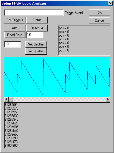
The above is the latest screen shot off of the logic analyzer dialog
box in my synthesizer consol program...and what is significant.
The wave form you see is exactly what I expected to see. I
finally got the mixer working properly...or at least, more properly.
I just have a few more tweeks to do, and then I start on the
final leg of trying to get the I2S interface to work so I can actually
hear what I have created. I still have not verified that all 512
channels work, but it sure looks like they do.
October 18, 2008
The first phase of my digital synthesizer is DONE! Now, while the
source code for all of this is pretty much in a shambles...because
speed of writing the code was more important than making it look good,
you will have to fogive the fact that in some places comments are
lacking.
In the archive you will find the following folders:
100-1056.....Cad files (Orcad
Schematic and Protel PCB) for the interface board I made to go between
the Spartan 3 Starter Board and the STK500/501
vga.....This is the Xilinx ISE
9.1 project for the FPGA portion of the project. You will notice
that there are a lot of extraineous source files in this folder because
I did go down some blind alleys. When I clean things up, I will
get rid of the extraneous files. Also, the reason this is called
vga is because of the fact that I did a VGA display for the spartan 3
Starter Board, and I use this to debug code. And I never bothered
to rename it...so don't let the name fool you. Included in here
you will find the logic analyzer I made to debug the hardware, the
single stepping hardware, also for debugging, Uarts, Timers, Static ram
interface. Everything interfaces to the external memory bus on an
ATmega2561.
AvrFpgaSynth....This is the
source code for the application portion of the AVR code. I use an
RTOS that I wrote myself. Besides the midi interface, I also have
an RS232 interface that I use to debug software and hardware.
AvrLib....this is my AVR
library...Some of the code I wrote myself....other parts were gleaned
for other sources and modified. My RTOS is included in the
library.
SynthConsol....this is a
program written using Microsoft Visual C++ 6.0. This program was
used to debug the hardware. It is not exactly done, but it got
the work done. In it you will find interfaces to the Logic
Analyzer and the Single Stepper.
Initial Release of Source code for FPGA synthesizer
Have fun...and don't turn this in as a homework assignment.
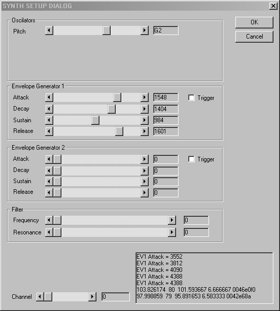
February 7, 2009
I
haven't been able to work on this much lately. The current status
is I have written the verilog code for the four pole low pass filter.
I just need to work it into the signal chain which means making
sure all the pipeline delays line up. I have tested the module
with the simulator, and it seems to be doing what it is supposed to be
doing. I am really hoping I can spend a little time on this soon.
Home