First Posted Feb 3, 2002
Updated 10-8-2007
Progress is good. Today, I actually hooked it up to my synthesizer (also a homebuilt) and made a short recording. This probably doesn't sound like much to most, but I need to remind those who don't know me, I don't have much in the way of musical tallent. If you listen carefully, the patch I am using makes the sequencer skip a step every other time it goes through. The "percusion" is generated using the patern generator.
Here are the latest.
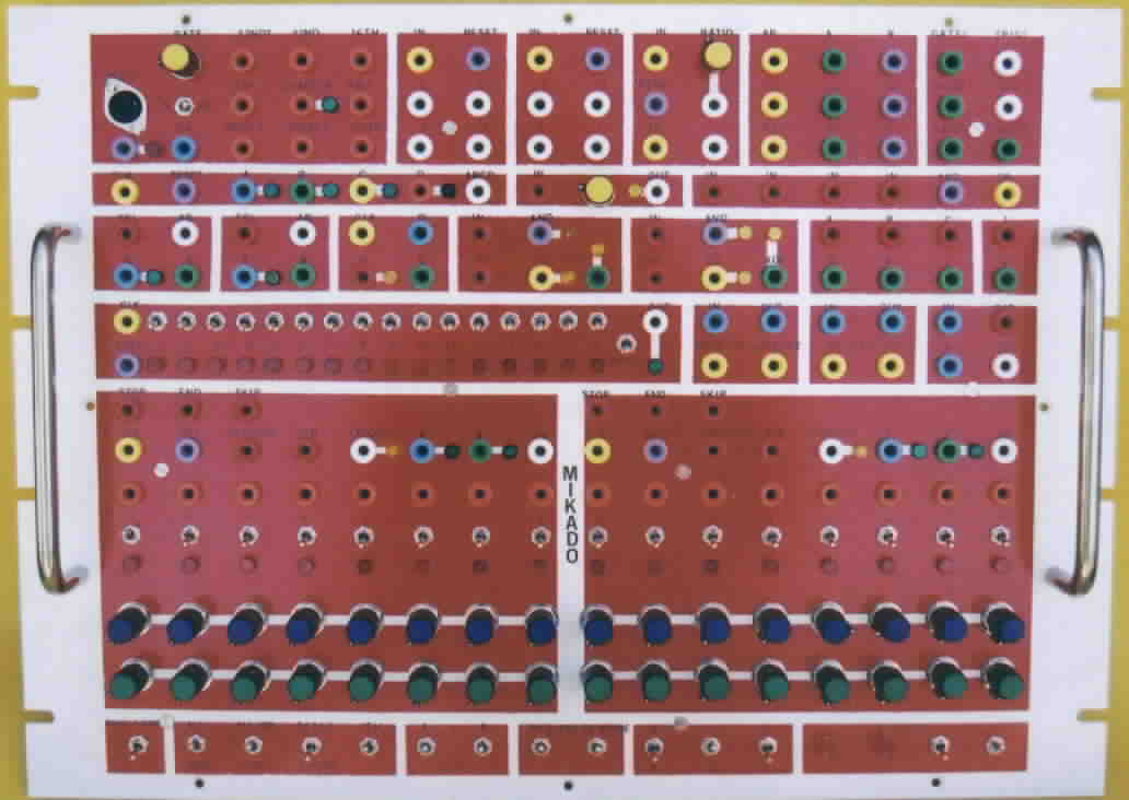
Picture of the front panel for my system
Picture of the back of the front panel
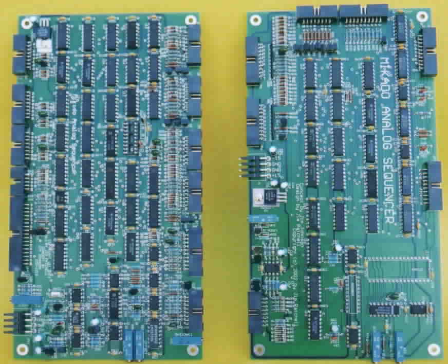
Picture of Board #1 and Board #2
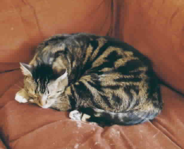
Picture of a really big
helper in this whole project
The picture of the front panel above you may notice the rather colorful aspect of the banana jacks...well, it turned out a little more colorful that I thought, and while I don't like the way it looks, well, I am too lazy to pull the jacks off and be a little more conservative. What I had hoped to accomplish was to make it easier for me to figure out which jack did which job....well, I failed....but thems is the breaks.
And of course, there is a picture of my little helper...he sure made doing the project interesting...and he even added a bit to the paint job on the panel.
This is a project that I am doing with Jim Johnson. It is a pretty involved circuit that is basically an analog sequencer on steroids.
The plan has been changed just a little bit. To save time, I have ended up putting the sequencer on three boards.
Board #1 contains the 8x2 sequencer and the quantizer. To make the full system, you will need two of these cards.
Board #2 Contains the Midi Interface, Master Clock, the Dividers, and Logic.
Board #3 Contains the Patern Generator, Analog Switches, One Shot, Transposer and Power Supply.
The current status is that the boards should go out
for a prototype run near the end of April. The plan is for the first
prototype unit to be completed by the end of May.
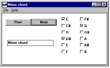
You will find that in the current version, there are a few things that do anything. Like File Load, Save As. File save will cause the program to generate a rom image for a 27C010 in the file quan.bin. This program is for Windows. It was compiled with Borland C++ Version 4.52.
Quantizer Look Up Table Generator (Includes Source)
See ya all later...