
Created Aug 1, 2001
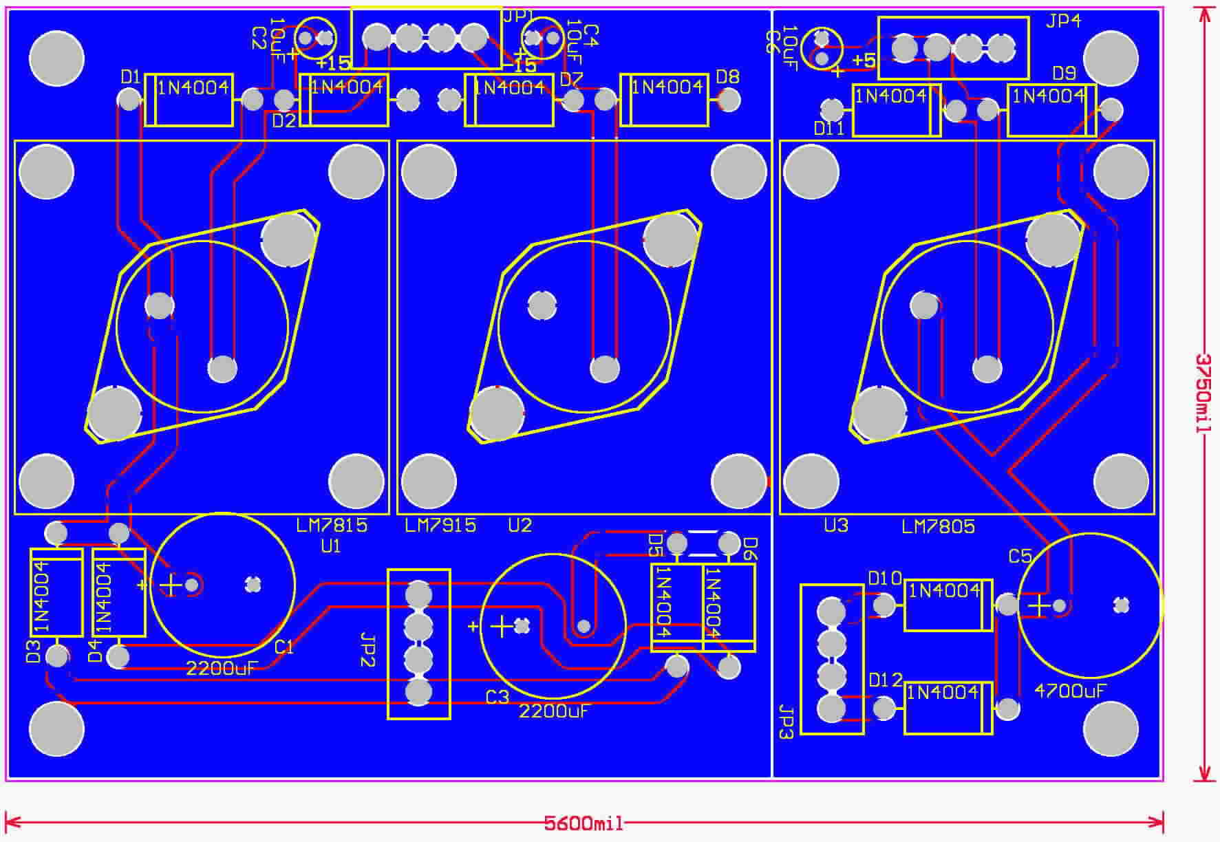
This is a very simple power supply board. It features very heavy copper traces and ground planes to keep noise down. In the picture below, the blue is the circuit side layer. The orange that you see peaking through is the component side copper.
The power supply requires a pair of transformers.
30 VCT -> 40VCT is needed for the +/- 15 volt supply, and 12.6 VCT -> 18
VCT is required for the +5 volt supply. It should be noted that the
higher the voltage, the more heat will be disipated by the regulators.
This heat will determine how much power you can get.
You will need some heatsinks for the card. I recomend these:
Mouser Part Number 532-568303b00
$4.17 This is the cadalac. Die cast. Very
rugged
Mouser Part Number 532-500403b00
$1.74 Stamped Metal, but, disapates more power than the
cadalac.
You will also need some transformers. Here are the ones I recomend. These are torriod transformers. Very low magnetic radiation.
Digikey Part Number TE62060 $13.32
2x7 VAC 25VA Transformer. Use for +5 volt power supply
Digikey Part Number TE62073 $14.85
2x15 VAC 35VA Transformer. Use for +/-15 volt supplies
Digikey Part Number TE62072 $14.85
2x12 VAC 35VA Transformer. Use for +/- 12 volt supplies
You do not need to insulate the regulator from the heat sink. But, I do recomend you put heat sink grease between the regulator and heat sink, or, use a sil pad if you don't like grease.
It shoud be noted that you can calculate the filter capacitance as such:
Capacitance (FARADS) = current (amps) / ( Frequency (Hz) * Ripple (volts) ).
To get uF (microfarads), multiply FARADS * 1,000,000.
|
|
|
|
|
|
| +/- 15 volts | 1 amp | 30VCT @ 1 amp | 4700uF | 7815K/7915K (TO-3) |
| +/- 12 volts | 1 amp | 24VCT @ 1 amp | 4700uF | 7812K/7912K |
| +/- 8 volts | 1 amp | 20VCT @ 1 amp | 4700uF | 7808K/7908K |
| +/- 5 volts | 1 amp | 18VCT @ 1 amp | 3300uF | 7805K/7905K |
| +/- 5 volts | 1 amp | 12.6VCT @ 1 amp
This will run cooler. |
10,000uF | 7805K/7905K |
| +/- 24 volts | 1 amp | 48VCT @ 1 amp | 2200uF | 7824K/7924K |
The single power supply is identical, except, it uses only the positive regulators (78xx) series.
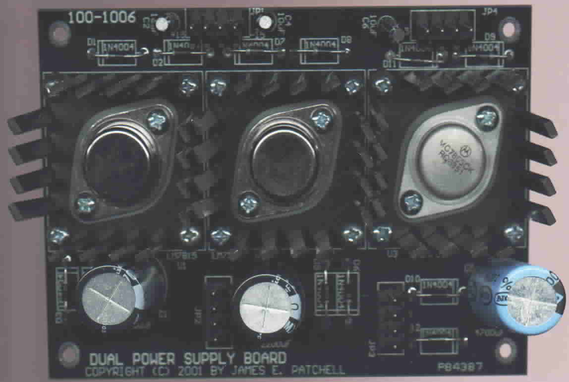
Picture of assembled board.
Before powering up, inspect the board for solder
bridges. The easiest place to have a solder bridge is on the output
bypass capacitors, C2, C4, C6. After connecting up the transformers,
you can power it up. If there is no smoke (most likely from capacitors
that are in backwards), it is probably working ok. Check the voltages
at the outputs. The +15 output should read very close to +15 (the
regulators are rated at +/- 0.25 volts tolerance), so the voltage could
vary from 14.75 to 15.25. Now, the -15 volt output will probably
not read -15, that is because the 79xx regulators require a minimum load.
Putting a 100 ohm load on the output should bring this close to -15 volts
(again, +/- 0.25). Finaly, check the +5 volt output (If you put it
on), it should be 4.75 to 5.25 volts.