This page is for the Rev A version.
If you have the N.C. Board (original) click here.
This is, believe it or not, the first analog sequencer I have ever done. There really isn't too much special about it, but here are the features.
8x2 Sequencer. 8 steps with two analog outputs.
Glide and shape on each output. Exponential
control is provided for these controls.
Output one features a "settled" output, which can
be used under certain circumstances to self clock the module
Inputs include clock, stop, end,
reset.
Power on reset. The module will always reset
to step 1.
LED drivers for each step.
Gate outputs for each step.
Input voltage range for the analog sequencer is
+/- 10 volts.
Schematic
Bill of Materials
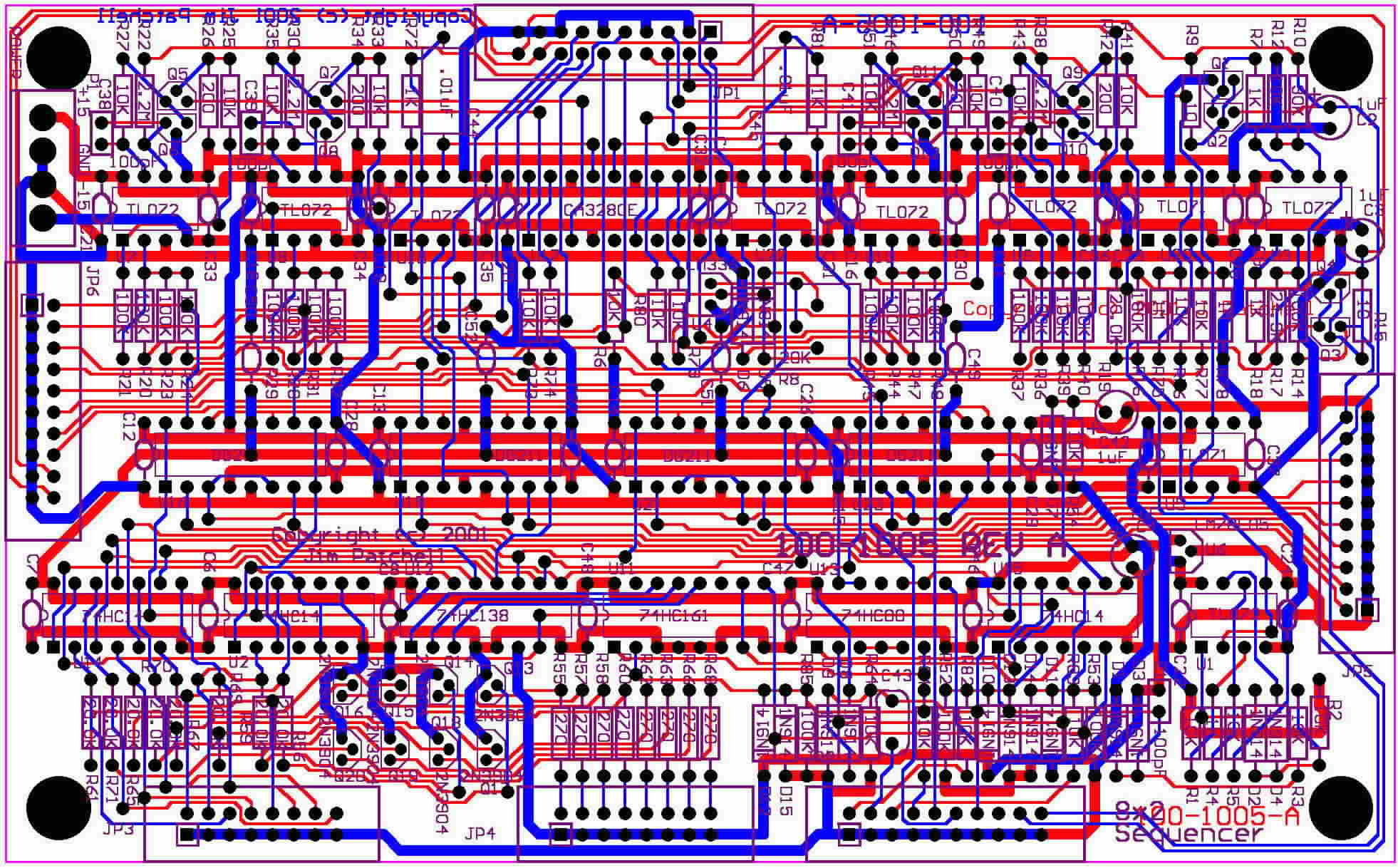
Printed Circuit Board Picture
(jpeg from Protel 2.7)
Clock
This input is used to step the sequencer one step on each rising edge. This input can be any voltage from a maximum of +/- 15 volts to a minimum of 0->5 volts.
Input low must be 0 volts
or less.
Input high must be 5 volts
or more.
This input is diode clamped to prevent damage to the parts inside.
End
This input is used to mark the end of the sequence. If for instance, you connect the GATE 4 output into the END input, the sequencer, when clocked, will generate the following sequence:
1-2-3-4-1-2-3-4-1-2-3-4......
If you connect the GATE 5 output into the END input, you will get the following sequence:
1-2-3-4-5-1-2-3-4-5-1-2-3.....
And so on and so forth.
Input low must be 0 volts or less.
Input high must be 5 volts or more
This input is diode clamped to prevent damage to the parts inside.
Stop
This input is used to stop the sequence. If for instance, you connect the GATE 6 into the STOP input, the sequencer, when clocked, will generate the following sequence.
1-2-3-4-5-6
And it will remain at step 6 until the sequencer is reset of the stop input in removed.
Input low must be 0 volts or less.
Input high must be 5 volts or more.
This input is diode clamped to prevent damage to the parts inside.
Reset
This input is used to reset the sequencer back to step 1. The reset will occure no matter what else is happening. If, for instance, you connect GATE 5 into the reset input, you will get the following sequence when clocked:
1-2-3-4-1-2-3-4-1-2-3-.........
Contrast this with the result you would have gotten if GATE 5 was connected to END (see the above example).
If you are using the STOP input, the reset input can be used to restart the sequece from step 1.
The reset input is capacitively coupled, which makes it trigger on the leading edge of the input. Because it is capacitively coupled, you will need a signal that has a fairly fast rise time in order to reset the module.
Gate1->Gate8
These outputs go high (+5 volts) during each step. So, Gate3 will be high during Step 3.
LED1->LED8
These outputs are used to light up an LED. These outputs consist of two lines. Even numbered pins on JP4 are connected to the collector of a transistor through a 270 ohm resistor, and the Odd numbered pins are connected to VCC (+5V). Normally, the Even numbered pins go to the cathode of the LED and the ODD numbered pins go to the anode.
IN1->IN8
These are the analog inputs. There is a set for both sections (refered to as 1 and 2). These inputs are high impeadence. The input voltage ranges is limited by the input buffer which is a TL072, so, if you are using +/- 15 volt supplies, the inputs can go from -13 to +13 volts.
Out1 and Out2
These are the analog outputs. Each output has a 1K resistor in series with it to isolate the opamp from capacitive loads and for short circuits protection.
Glide
Each section has a glide. The glide consists of three inputs that are summed together. The glide input affects the glide exponentially.
Shape
The shape control adjust weather the glide settles in a linear (slewing) or exponential (RC time constant) fashion. The shape inputs consist of three inputs that are summed together. This control responds exponentially to the control voltage (not to be confused with the fact that it controls the exponential settling of the glide circuit).
Settled 1
This output is high when the output for section 1 has settled, and goes low when the output is slewing. This output can be used to self clock the sequencer by connecting it into the clock input. However, there are a lot of gotcha's with this. If two steps are set to the same voltage, this output will not change and so it will stop clocking.
JP1--Glide and Shape Controls
1....Glide Channel 1
2....Glide Channel 1
3...Ground
4...Glide Channel 1
5...Shape Channel 1
6...Shape Channel 1
7...Ground
8...Shape Channel 1
9...Glide Channel 2
10...Glide Channel 2
11...Ground
12...Glide Channel 2
13...Shape Channel 2
14...Shape Channel 2
15...Ground
16...Shape Channel 2
17...Ground
18....+10Volts
19....Ground
20....-10Volts
JP2---Inputs/Outputs
1....Ground
2....Stop
3....Ground
4....Reset
5....Ground
6....End
7....Ground
8....Clock
9....Ground
10....Out 1
11....Ground
12....Out 2
13....Ground
14....Channel 1 Settled (1=Settled, 0=Unsettled)
15....Ground
16....No Connect
17....Ground
18....+10Volts
19....Ground
20....-10Volts
JP3---Gate Outputs
1....Ground
2....Gate Step 1
3....Ground
4....Gate Step 2
5....Ground
6....Gate Step 3
7....Ground
8....Gate Step 4
9....Ground
10....Gate Step 5
11....Ground
12....Gate Step 6
13....Ground
14....Gate Step 7
15....Ground
16....Gate Step 8
JP4---LED Outputs
1....VCC
2....LED Step 1
3....VCC
4....LED Step 2
5....VCC
6....LED Step 3
7....VCC
8....LED Step 4
9....VCC
10....LED Step 5
11....VCC
12....LED Step 6
13....VCC
14....LED Step 7
15....VCC
16....LED Step 8
JP5---Inputs 1 and JP6---Inputs 2
1....Ground
2....Input 1
3....Ground
4....Input 2
5....Ground
6....Input 3
7....Ground
8....Input 4
9....Ground
10....Input 5
11....Ground
12....Input 6
13....Ground
14....Input 7
15....Ground
16....Input 8
17....Ground
18....+10 Volts
19....Ground
20....-10 Volts