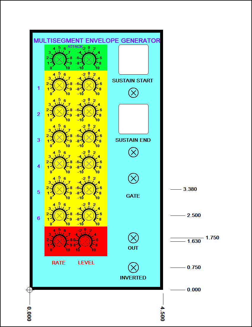
Also, you can select which step will be the sustain step. By sustain, I mean where will it stop while the key is being held down. So, if you set the sustain for step 3, it will progess though the steps 1->3 and as long as the gate remain true, it will hold at step 3. When the gate is release, it will sequence through the rest of the steps until it gets to the last one, and then return to the release state (which is always step 0).
The steps are numbered 0 -> 7, with like I said above, step 0 is always the release state. All of the voltage inputs for both the rate and level can be set between +10 volts to -10 volts (this assumes a +/-15 volt supply). The Gate input trips at about 2.5 volts and can be any voltage from -15 to +15 volts (this input is diode protected).
There are LED drivers for each step and for each state. The four states are State0 (Release), State1 (Attack), State2 (Sustain), State3 (final decay). So, it is posible to have lots of LEDs on your panel if it is so desired. I personally am for right now just using the step LED's (when I build the module).
Please note, the schematic is very preliminary. There are likely to be some errors on it. I have not yet had the time to test this circuit. I have simulated the logic, but that is it.
I do have plans in the near future to do a PC board, but, my ecconomic situation is going to have to improve before I can consider such a thing
Several changes have been made since I posted this first, back in March.
1. The descrete logic has been removed in favor of a PLD (22v10). This became nessesary because the logic just would not fit on the size board I had in mind (4.5" x 4.0"). The VHDL code is down below, if you want to take a peek. The code was compiled with the Cypress Warp CPLD compiler.
2. Originally, I was going to have LEDs for both the State and the Sequence, but, again, there just wasn't enough room on the board for all that, so, the STATE LEDs were dropped. There is still one LED for each step.
3. I am planning on ordering a prototype run of
the
boards on June 3, 2002. I hope this thing works as good as I
hope.
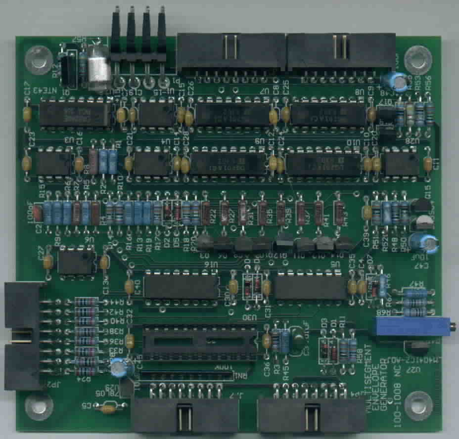
The boards have come in. The first one has been assembled. You can view the picture down below.
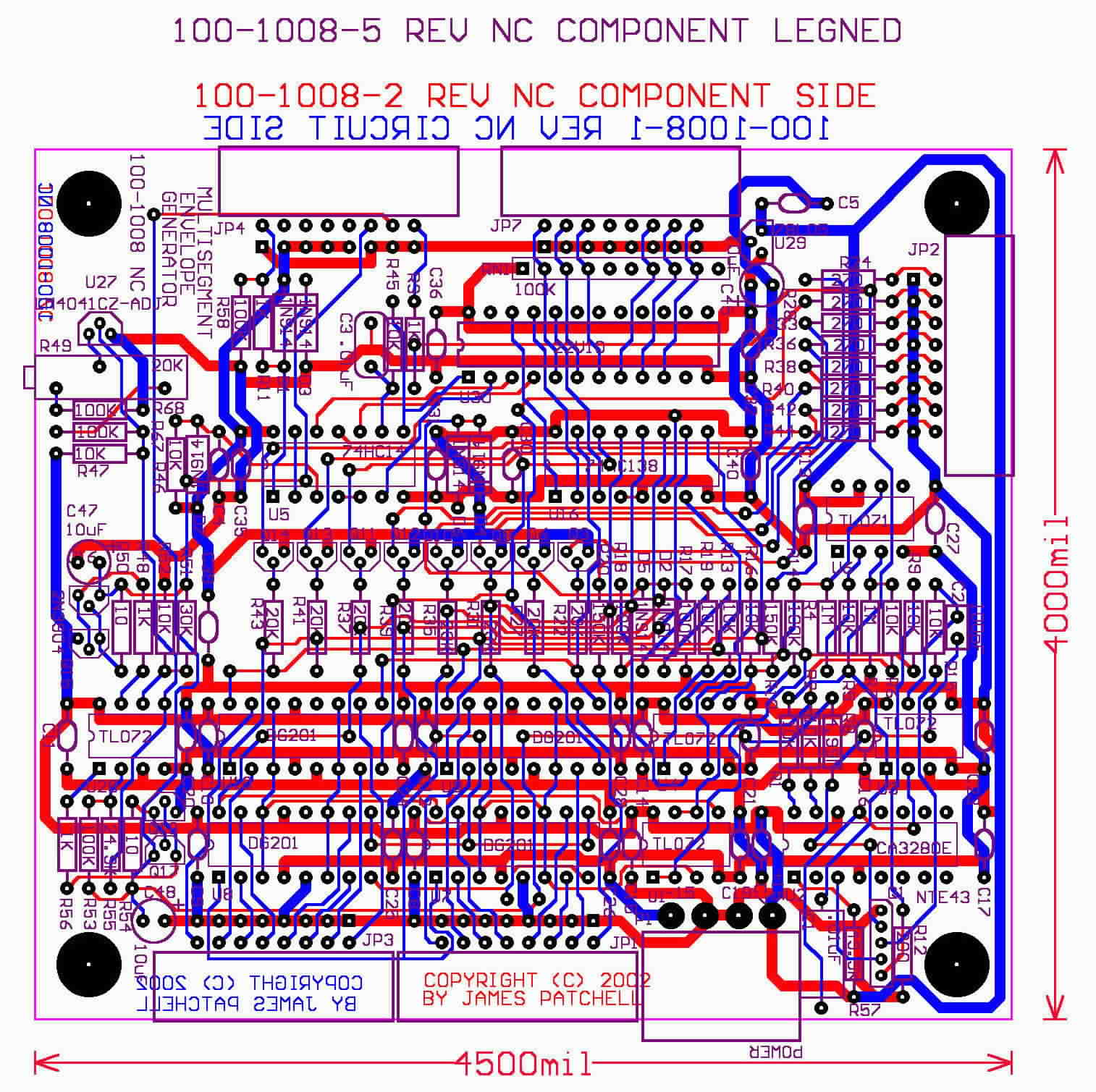
Picture of PC board Layout (not the real board)
Latest Update as of October 20, 2002
Well, I got the damn thing working. There were several problems. The biggest one was control feedthrough in the OTA based lag circuit. While the CA3280 has very low feedthrough, in this circuit, what it did have became a very big deal. I used a rather high gain circuit to determine when the envelope had settled to it's intended value. Then the feedthrough became a big deal...to solve this, Jurgen Haible gave me permision to use his substitute circuit. It is a cleaver little circuit that is just pefect for lag circuits like this one. The second problem is that in the original circuit, I used a differential amplifier to subtract the goal voltage from the actual voltage, and it had common mode problems. A new circuit was put in to do the subtraction that does not suffer from common mode problems.
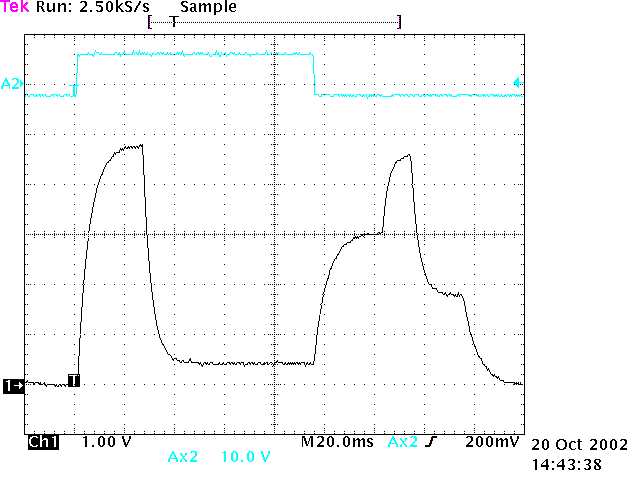
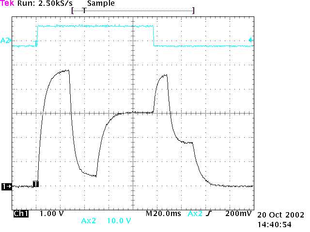
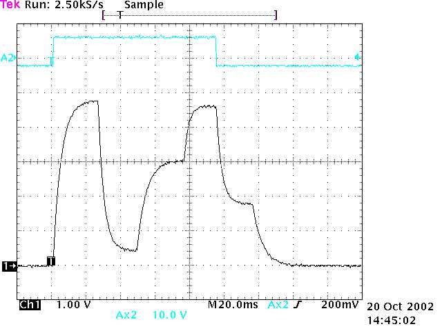
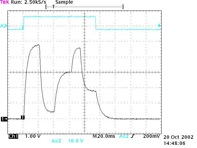
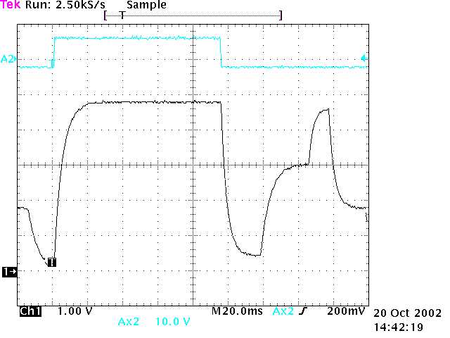
I am still in the process of updating the schematic, so for now, you will have to look at the old one. Here are some scope pictures I took.
The pictures demonstrate on of the powerful features of this envelope generator. It is posible to select which segment it will sustain on. I am using only 6 segments of the posible 8, since that is all I had room for on my front panel in the way of pots. The pictures are in order of sustaining on segment 1 to segment 5...it makes no sense to sustain on the last segment, which is the release segment.
Here is an MP3 file that uses the multisegment envelope generator with the vocal filter...File is about 500K
This is another MP3
file,
but this one is just one trigger sequence of the envelope generator,
and
it goes fairly slow so you can hear the 6 segments. This is the
same
patch as was used in the above, but just one note. Actually, this
shows off the vocal filter a little better too.